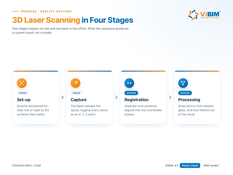
3D laser scanning is a non-contact measurement method that uses a laser beam to measure the distance to every surface it can see, producing a dense set of three-dimensional coordinates for an object, a building, or an entire site. The work runs in four stages, set-up and capture on site, then registration and processing back in the office, and it stops at a point cloud, well short of a model.
Scanners reach those measurements three ways, by timing a pulse, by comparing the phase of a returning beam, or by triangulating a projected line, and working range turns out to be a property of the scanner rather than the technology. How dense and how complete the resulting cloud is then sets the ceiling on the LOD anyone can model from it. Everything a project team dimensions afterwards traces back to that one file, so a capture taken at the right density answers questions for years without a return visit, while one that missed surfaces leaves a modeling team inferring geometry nobody measured. The sections below define 3D laser scanning in workflow terms, weigh what it is good for, show where AEC teams use it, and set out what a scan must contain when planning how to make scans for BIM modeling, and what to settle before commissioning one.

What Is 3D Laser Scanning?
3D laser scanning is the reality-capture step that records an existing building or site before design work begins, replacing manual dimensioning with a measured digital record of what is actually there. Survey and engineering teams reach for it when drawings are missing, outdated, or too coarse to build from.
3D laser scanning differs from neighboring survey methods by coverage, not precision alone. A total station measures discrete points one at a time, and photogrammetry derives geometry from overlapping photographs. A scanner sweeps the whole space and records surfaces nobody thought to single out, so a late question about a ceiling void can often be answered without a second site visit.
The output is not a drawing and not a model. A scan session ends with a point cloud, a set of measured coordinates describing every surface the laser reached. As-built drawings, Revit models, and clash checks are all built from that file, so what the scanner captures sets the limit on everything produced afterwards.
How Does 3D Laser Scanning Work?
3D laser scanning works by emitting rapid laser pulses, measuring how each pulse returns from a surface, and converting those measurements into millions of X, Y, Z coordinates that together form a point cloud. The work splits across two settings, fieldwork on site and processing in the office, and runs through four stages:
- Set-up (field). The scanner is positioned where it has clear line of sight to the surfaces that matter, because the laser records only what it can see.
- Capture (field). The head rotates and sweeps the beam across the space, logging each return as a coordinate point. One position rarely covers a room, so the scanner is moved and the sweep repeated from several vantage points.
- Registration (office). The separate scans are aligned into a single coordinate system using the overlapping areas shared by neighboring positions.
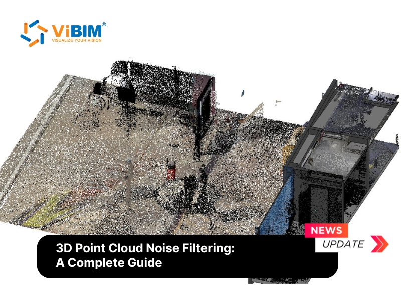
- Processing (office). Stray returns from moving people, reflective glass, and airborne dust are filtered out, leaving a cloud that Scan to BIM software for Revit and other modeling tools can open.
A survey-grade terrestrial scanner records on the order of a million points per second and holds millimeter-level accuracy, commonly quoted between 2 mm and 4 mm at normal working distances. That density is what makes the method fast on site. A room that would take a two-person crew an afternoon to dimension by hand is captured in a few minutes per position.
Line of sight is the limit that matters. A laser cannot see through a duct, behind a column, or above a suspended ceiling tile, so anything the beam never reached does not exist in the data. Adding positions closes those gaps, and how many to add is judged on site, not corrected later.
What a completed scan hands over is a point cloud, not a model. The cloud records where surfaces are, but nothing in it knows that one cluster of points is a wall and another is a duct. Turning those coordinates into geometry a project team can schedule and coordinate from is separate work, and usually a separate team.
Field capture and modeling are usually bought as separate jobs. ViBIM’s point cloud to BIM services cover the second half, turning a registered cloud into Revit geometry at an agreed LOD for survey and reality-capture firms that keep their own crews on site work.
The Three Types of Laser Scanner Technology
Laser scanners use three ranging technologies: time-of-flight, phase-shift, and triangulation. Their working ranges overlap far more than the usual textbook split suggests.
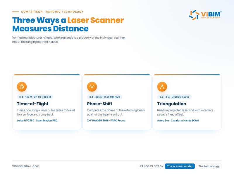
| Technology | Verified working range | Precision reference | Typical use | Example scanners |
|---|---|---|---|---|
| Time-of-flight | 0.3 m to 130 m (Leica RTC360); up to 1,000 m (Leica ScanStation P50) | 2 mm to 4 mm at working distance | Open sites, exteriors, infrastructure, longest reach | Leica RTC360, Leica P50 |
| Phase-shift | 0.3 m to 365 m (Z+F IMAGER 5016); 70 m to 400 m across FARO Focus models | 0.25 mm rms range noise (Z+F IMAGER 5016) | Interiors, plant rooms, dense MEP | Z+F IMAGER 5016, FARO Focus |
| Triangulation | 0.5 m to 2 m | Micron-level | Individual objects and components | Artec Eva, Creaform HandySCAN |
Phase-shift is routinely described as the medium-range option, yet the Z+F IMAGER 5016 reaches 365 m while the time-of-flight Leica RTC360 stops at 130 m. The FARO Focus, cited across the industry as a time-of-flight scanner, measures by phase shift according to FARO’s own manual. Range is a property of the model on the tripod, not of the ranging method, and specifying a scanner by technology alone will mislead you.
Time-of-Flight Scanners
Time-of-flight scanners measure distance by timing how long a laser pulse takes to travel to a surface and come back. The calculation is direct:
Distance = (Speed of Light × Time-of-Flight) / 2
Alongside distance, the scanner logs the horizontal and vertical angle of every pulse, covering a full 360° horizontally and roughly 330° vertically from each position. Combining distance with angle places each return as a coordinate in space. Time-of-flight scales to the longest reaches available, which is why it holds the open-site and infrastructure work. The Leica RTC360 covers 0.3 m to 130 m, and the ScanStation P50 pushes to 1,000 m.
Phase-Shift Scanners
Phase-shift scanners measure distance by comparing the phase of the outgoing beam against the phase of the beam that returns. The relationship is expressed as:
Time-of-Flight = Phase Shift / (2π × Modulation Frequency)
Because the comparison runs continuously rather than pulse by pulse, phase-shift units capture faster and hold lower range noise than time-of-flight at the same distance. The Z+F IMAGER 5016 quotes 0.25 mm rms range noise and reaches 365 m. That precision suits interiors, plant rooms, and any space where pipework and conduit sit close enough that a coarse cloud would blur them together.
Triangulation Scanners
Triangulation scanners measure distance by projecting a laser line onto an object and reading where that line lands with a camera set at a known offset. The fixed distance between camera and laser source resolves the geometry trigonometrically.
Triangulation works between 0.5 m and 2 m at micron-level accuracy, which places it outside building survey. The method suits component inspection and reverse engineering, on units such as the Artec Eva and Creaform HandySCAN.
Choosing between specific models is a separate exercise from choosing a technology, and our roundup of the top 15 3D laser scanners for Scan to BIM compares current hardware in detail.
Benefits of Laser Scanning for Survey and Construction Work
Laser scanning offers four benefits on a live project: faster documentation, safer data collection, less rework downstream, and a dated record of existing conditions. Each one lands at a different stage of the job.
- Faster documentation. Scanning cuts surveying and documentation time by up to 80% against manual measurement, which is what makes it workable on buildings that cannot be closed for long.
- Safer data collection. The scanner measures without contact and without access, so live plant rooms, roof voids, and structurally unsound areas are recorded without sending anyone into them.
- Less rework downstream. Design that starts from measured conditions rather than assumed ones catches conflicts on screen instead of on site, where changes cost far more.
- A dated record of conditions. The cloud fixes the state of a building on a given day, which stays useful for handover, dispute, and any retrofit that arrives years later.
The size of each gain tracks the quality of the capture, which is why the same technology produces very different outcomes on two similar buildings.
Where Laser Scanning Is Used in AEC
Laser scanning is used across AEC wherever a project has to work from what exists rather than what was drawn: as-built documentation, renovation, plant and MEP coordination, heritage recording, and construction verification. The scope of a scan shifts with what the deliverable has to support.
| Application | What gets scanned | Typical deliverable |
|---|---|---|
| As-built documentation | Structure, envelope, and core of the existing building | As-built drawings and a Revit model |
| Renovation and retrofit | Zones being altered plus their interfaces with what stays | Coordinated model of existing and proposed |
| Plant and MEP coordination | Pipework, ducting, cable tray, equipment, structural steel | Discipline models and a clash report |
| Heritage recording | Ornament, vaulting, and facade detail | High-detail model and measured drawings |
| Construction verification | Work in place at a given date | Deviation report against the design model |
As-Built Documentation and Renovation
Renovation depends on as-built accuracy because every new element has to meet something that is already there. Drawings for older buildings are frequently missing, superseded, or drawn to an intent that construction never followed. Scanning replaces that guesswork with measured geometry, and the resulting model carries both the structure and the services a designer has to work around.
Industrial Plants and MEP Coordination
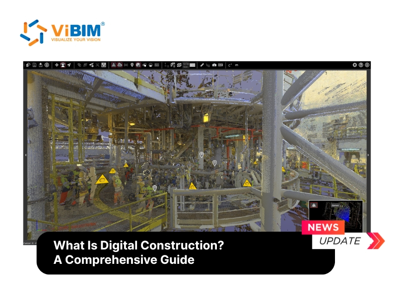
Industrial and plant environments are the densest thing a scanner is asked to record. Pipework, ducting, and cable tray occupy the same volume in layers, and hand measurement cannot resolve them at a usable tolerance. A registered cloud gives each discipline a common reference, which is what makes coordination possible before fabrication rather than after.
Heritage and Cultural Buildings
Heritage recording asks for detail that a design-intent model never carries. Moldings, vaulting, and weathered facade profiles are geometrically irregular, so they have to be measured rather than approximated from a family library. Scanning captures that irregularity, and conservation work is then documented against it.
Outside AEC, the same technology serves manufacturing inspection, reverse engineering, and forensic recording, though the scanners and tolerances involved differ from building work.
How Point Cloud Quality Determines the LOD You Can Model
Point cloud quality determines the LOD you can model by fixing how much real geometry exists in the data for a modeler to trace, and the same ceiling applies when you convert point cloud to 3D model geometry. Three properties decide that, and each one fails in a different way.
- Point density. Density sets the smallest feature that survives. A coarsely sampled cloud still shows a wall, but a small-diameter conduit or a molded reveal falls between points and has to be inferred rather than measured.
- Coverage. Gaps in the capture become gaps in the model. A modeler facing an absent riser has two options and neither is good. They assume a route, or they raise a query and wait.
- Registration accuracy. Small misalignments between scan positions compound across a building, so geometry that looks clean in one room has drifted by the time it reaches the far end.
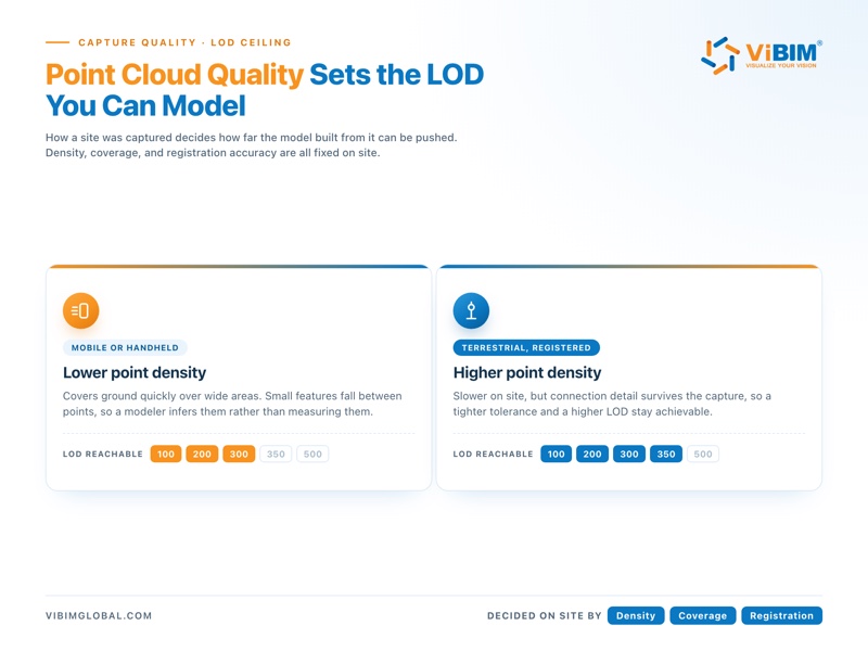
LOD is a specification for how much a model asserts, and every level above the basic assumes the geometry behind it was actually measured. Asking for LOD 350 from a cloud that cannot resolve connection detail produces a model that looks compliant and is not.
Capture method is where all three properties get decided.
| Capture method | Point density | Practical LOD ceiling | Best suited to |
|---|---|---|---|
| Mobile or handheld, such as BLK2GO | Lower | Around LOD 300 across the model | Fast capture over wide areas |
| Terrestrial, registered | Higher | Supports higher LOD and tighter tolerance | Projects where accuracy and detail drive the deliverable |
We have modeled from both. Mobile scanning covers ground quickly, but its lower point density puts a ceiling on how far LOD can be pushed, and around LOD 300 across the whole model is a realistic expectation rather than a fault in any one device. Where a project needs fine detail, a terrestrial scan with a properly registered cloud is what we ask for. That cloud is the reliable starting point for point cloud 3d modeling.
Scan quality also sits alongside scope, LOD, LOI, tolerance, project size, and coordination requirements as one of the factors that sets what a modeling job costs. Two buildings of identical size can carry very different modeling effort depending on what arrived in the file. Across 250,000 hours of Scan to BIM delivery, the clouds we work from were captured by other people’s scanners, so reading a cloud for what it will support comes before quoting against it.
What Do You Need to Turn a Laser Scan Into a BIM Model?
You need three things to take point cloud data to BIM: point cloud files in a format the authoring software can open, a written specification for LOD and tolerance, and a team with the capacity to build it. The first is a technical question about formats and transfer, the second is a commercial one about what the deliverable has to do, and the third is where most survey firms decide between building in-house and sending the work out.
What File Formats Are Used for Scan Data?
Scan data is delivered mainly as RCP and RCS files, with E57 as the vendor-neutral alternative and zipped datasets for bulk transfer. RCP and RCS are the formats we prefer to receive, because they open directly in the Autodesk toolchain without a conversion step. E57 works, though it usually needs converting before modeling starts.
Practical limits matter as much as format. We ask for RCS files at 5 GB or under, or a single zip per transfer, which keeps handover reliable across FTP, Box, Google Drive, Cintoo, and Autodesk Construction Cloud. Models leave as RVT, as IFC with the schema version stated, and as DWG for 2D sheets. A fuller breakdown of each option sits in our guide to point cloud file formats.
Working With an Outsourced Modeling Team
An outsourced modeling team takes the point cloud and returns the deliverable, which lets a scanning firm keep its own capacity on field capture. We work as a production extension for survey and reality-capture firms rather than as a competitor for their fieldwork.
A scope, timeline, and price for our Revit modeling services come back within 12 to 24 hours of receiving project details, a dedicated project manager is assigned on approval, and a typical project runs one to three weeks. Delivery holds a 99% on-time record, turnaround averages 30% faster than the market, and output is produced against ISO 19650, PAS 1192, and the BIM Forum LOD specification. New clients start with a free trial project, which also calibrates our output to their QC standard. The full scope sits on our point cloud to BIM services page.
What Makes a Point Cloud Unusable for Modeling?
A point cloud becomes unusable when the geometry a modeler needs is missing, misaligned, or buried in noise. Our review runs in two independent passes, and the failures they catch are consistent.
Geometry that was never captured, because the scanner had no line of sight into a riser or above a ceiling. Positions that did not register cleanly, so the same wall appears twice a few millimeters apart. Parameters and data that arrived incomplete, leaving elements that cannot be classified. Deviation between the cloud and what the drawings claim, which has to be resolved rather than modeled around.
None of these are fixable in modeling software. They are fixed by going back to site, which is why a cloud is worth reading before the modeling schedule is set.
What Should You Know Before Commissioning a Laser Scan?
You should settle three questions before booking a scan: whether the job needs LiDAR or close-range scanning, what accuracy the deliverable genuinely requires, and what the scan costs against the work it replaces.
Is 3D Laser Scanning the Same as LiDAR?
No, though the two overlap more than most explanations admit. LiDAR names the ranging principle, measuring distance with light, and terrestrial laser scanners use it. That is why many sources describe scanning as LiDAR-based.
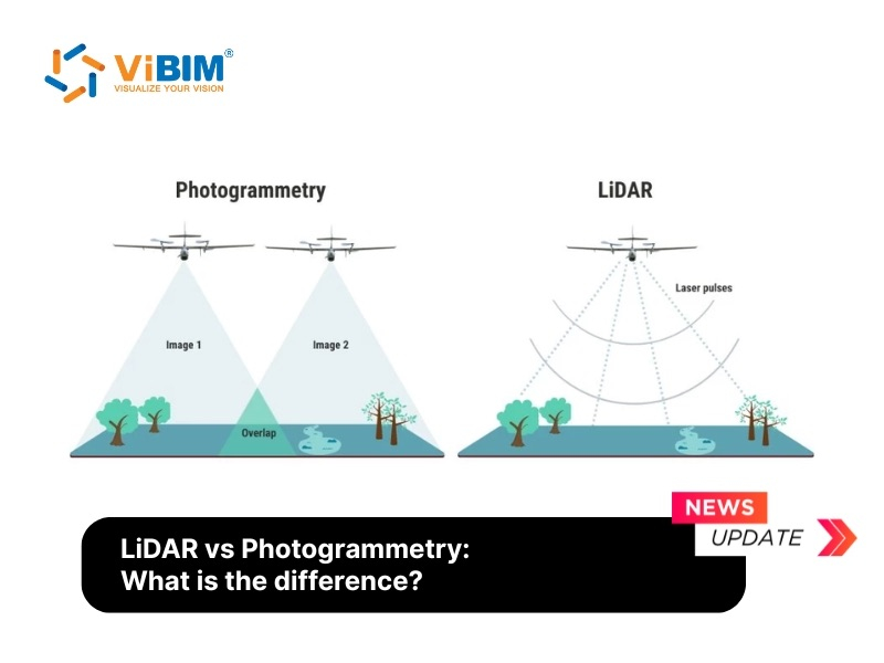
In working practice the industry reserves LiDAR for long-range airborne or mobile capture, such as terrain and corridor mapping, and uses laser scanning for close-range, high-resolution work on structures. Both descriptions are defensible, so it is worth confirming which one a supplier means. The difference is worked through in our comparison of LiDAR vs laser.
How Accurate Is a 3D Laser Scanner?
A 3D laser scanner resolves to somewhere between sub-millimeter and several millimeters, depending on the unit and the distance to the surface. Manufacturer figures describe the instrument under favorable conditions.
What reaches a model is also shaped by surface reflectivity, registration quality, and how many positions were used. Scanner accuracy and model accuracy are not the same number, and a specification should state the tolerance the deliverable has to meet rather than quoting the instrument alone.
How Much Does 3D Laser Scanning Cost?
3D laser scanning is priced on the size and complexity of the site, the accuracy required, and the deliverables attached to it, so quoted figures range widely. Field capture and the modeling that follows are usually costed separately.
Modeling is where the specification does most of the work, because one cloud can be modeled at several different LODs at meaningfully different prices. Our breakdown of Scan to BIM cost sets out the factors in detail.