Types of construction drawings are the categories a drawing set is divided into, and there are four independent ways to divide one. A construction drawing is a scaled technical document that communicates graphic and written instructions for building a structure. It records dimensions, materials, spatial relationships, and assembly sequences for every building component, from foundation footings to roof parapets.
Seven engineering disciplines each keep their own sheet series, running from the C-series for civil work to the FP-series for fire protection. View type cuts across all seven, because a plan, a section, and an elevation are vantage points rather than trades.
Project phase separates the design team’s sheets from the shop drawings and as-built drawings that arrive after contract award. Issue status changes what one sheet is allowed to be used for, from a preliminary print through to the record set handed over at closeout.
Because most published lists pick one of those axes and present it as the whole picture, two guides to the types of construction drawings can look nothing alike and both be accurate. Working with a real set also means knowing how the sheets are produced, how to read one, and what the abbreviations printed on it stand for.

What Is a Construction Drawing?
A construction drawing is one sheet within the contract document set, drawn to scale and read through standardized graphic conventions that architects, engineers, contractors, and building officials all interpret the same way. Every line, symbol, dimension, and annotation follows those conventions, which is what lets a drawing produced by one party be built by another.
Three other terms circle the same territory, and they are not interchangeable.
- Construction Documents, often shortened to CDs, are the finalized package of drawings and written specifications issued after Design Development. Under the AIA framework the package functions as a legal contract instrument.
- Working drawings are the drawing portion of that package, as opposed to the specifications, which carry the written requirements. The term is still in active professional use.
- Blueprints is a legacy term from the era of blue-line reproduction. People still say it, though nothing has been printed in blue for decades.
- Construction plans, or simply “the plans”, is what most site conversations call the same package. Nothing in the term distinguishes discipline, view, or issue status, which is why it is the loosest of the four.
Throughout this guide, “construction drawings” carries its broadest sense, covering the types of building drawing produced before, during, and after construction.
A construction drawing set is organized by discipline, and every sheet carries a prefix letter identifying where it came from. A sheet numbered A-201 is the first elevation sheet in the architectural set; S-301 is the first detail sheet in the structural set.
That convention comes from the CSI Uniform Drawing System, which the National Institute of Building Sciences publishes as part of the US National CAD Standard, and it is what lets anyone locate one sheet inside a set of several hundred.
Every sheet also carries a title block in the lower-right corner. It is the first thing to read on any sheet, because it tells you which discipline the sheet belongs to, which version you are holding, and who takes professional responsibility for its content.
With dozens of sheet types in a single set, a classification framework helps project teams find the right drawing for the right task.

The distinction between Schematic Design, Design Development, and Construction Documents marks a formal progression: each phase builds on the last with greater detail and legal weight. For a deeper look at how these phases connect, see what is SD DD CD means.
How Many Types of Construction Drawings Are There?
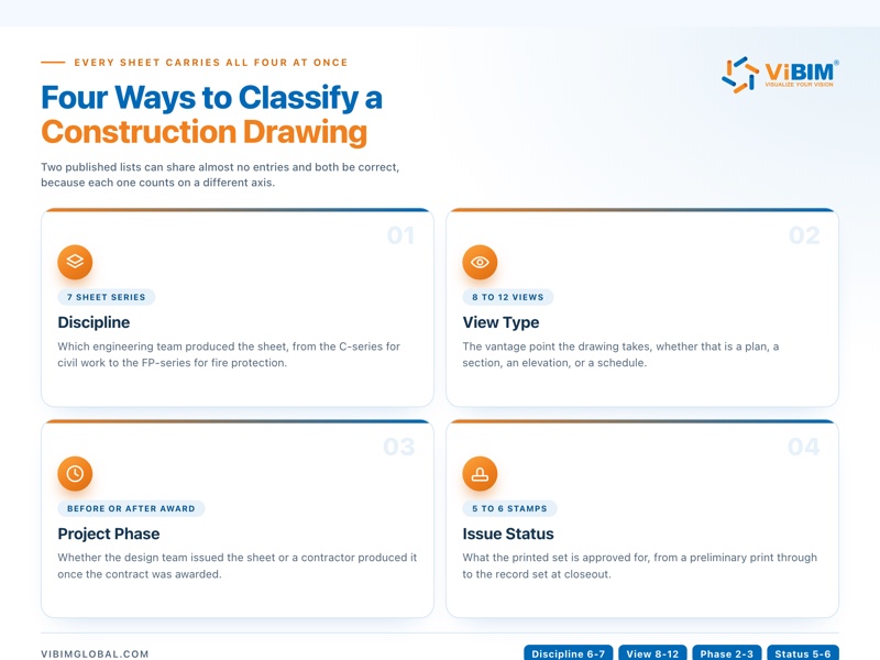
There is no single number, because construction drawings are counted along four different axes, and each axis produces a different total.
The number quoted most often is six. The 6 types of construction drawings taught in trade training curricula are civil, architectural, structural, mechanical, plumbing, and electrical. This guide counts seven, because fire protection maintains its own sheet series and answers to its own reviewing authority.
Lists that merge all four axes into one flat sequence of drawing types in construction can run past forty entries, which is how two published counts end up differing by a factor of eight without either being wrong.
The four counting axes are compared below.
| Counting axis | What it counts | Typical count | Example |
| Discipline | engineering trades that each keep their own sheet series | 6 to 7 | civil, architectural, structural, mechanical, electrical, plumbing, fire protection |
| View type | vantage points a drawing takes on the building | 8 to 12 | floor plan, elevation, section, detail, reflected ceiling plan, schedule, site plan |
| Project phase | when the drawing enters the project timeline | 2 to 3 | design set, shop drawings, as-built and record drawings |
| Issue status | what the printed set is approved for | 5 to 6 | design, tender, permit, issued for construction, conformed, record |
Asking how many types of drawing in construction exist is therefore the wrong question. The useful question is which axis you are counting on, because that is what tells you where to look in the set. It also explains why two published lists of the different types of construction drawings can share almost no entries and both be correct.
How Are Construction Drawings Classified?
Every construction drawing carries four attributes at the same time: the discipline that produced it, the view it takes, the project phase it belongs to, and the status stamped on the printed set.
One sheet can be architectural by discipline, a floor plan by view, part of the Construction Documents by phase, and stamped Issued for Construction by status. Naming all four locates that drawing exactly. Naming one leaves three questions open.
The axes divide the set up differently. Discipline and view type apply to every sheet the design team issues. Project phase separates those sheets from the ones contractors produce after contract award, and neither shop drawings nor as-built drawings carry a discipline prefix.
Status behaves differently again. The first three axes sort sheets into groups, while status attaches to one sheet over and over as that sheet is reissued.
For a focused comparison of the two phase-based types, see difference between as built and shop drawings.
Floor plans, sections, and elevations sit on the view axis rather than forming categories of their own. An architectural plan shows walls and rooms, a structural plan shows beams and columns, and a mechanical plan shows ductwork. Same view, different content. Because that view recurs inside every discipline, it earns an axis instead of a place in the architectural set.
The table below maps the main types of construction drawings to their producer, sheet series, project phase, and the views they typically use.
| Classification | Drawing Type | Produced By | Sheet Series | Project Phase | Typical view types |
| Discipline-based | Civil and Site Drawings | Civil Engineer | C-series | Design → CD | site plan, grading plan, utility plan |
| Discipline-based | Architectural Drawings | Architect | A-series | Design → CD | plan, elevation, section, detail, RCP, schedule |
| Discipline-based | Structural Drawings | Structural Engineer | S-series | Design → CD | framing plan, section, connection detail |
| Discipline-based | Mechanical (HVAC) Drawings | Mechanical Engineer | M-series | Design → CD | plan, riser diagram, equipment schedule |
| Discipline-based | Electrical Drawings | Electrical Engineer | E-series | Design → CD | plan, single-line diagram, panel schedule |
| Discipline-based | Plumbing Drawings | Plumbing Engineer | P-series | Design → CD | plan, riser diagram, isometric |
| Discipline-based | Fire Protection Drawings | FP Engineer | FP-series | Design → CD | plan, riser diagram, hydraulic calculation sheet |
| Phase-based | Shop Drawings | Contractor / Fabricator | N/A | Post-award | fabrication detail, assembly, piece drawing |
| Phase-based | As-Built and Record Drawings | Contractor (closeout) | N/A | Post-construction | plan, section, elevation, schedule |
What determines which types of construction drawings a project needs? Scope, building type, local code requirements, and contract structure. A single-family home may require 20 to 30 sheets. A mid-rise hospital can exceed 500.
The following sections examine each axis, starting with the disciplines that form the backbone of every set.
Construction Drawings by Discipline
The seven construction disciplines are civil, architectural, structural, mechanical, electrical, plumbing, and fire protection, and each one maintains its own sheet series with a standard prefix letter.
A discipline in construction is an engineering field responsible for one building system, staffed by its own licensed professionals and filed under its own sheets. The discipline axis is the one most people mean when they list types of construction drawings, because it maps directly onto how design teams are organized.
All construction disciplines coordinate against a common reference: the architectural floor plan. MEP engineers overlay their systems on it. Structural engineers reference it for column grids and load paths. This coordination happens through design meetings and BIM clash detection tools like Navisworks or Autodesk Construction Cloud.
On a typical commercial project, the architectural set is the largest by sheet count, MEP follows close behind, and the structural set carries the highest liability per sheet.
Below is a detailed look at each discipline, from civil site work through fire protection.
Civil and Site Drawings (C-Series)
Civil drawings are the sheets that document everything outside the building envelope: property boundaries, grading, drainage, utilities, and access routes. Civil engineers produce these under the C-series prefix, and building officials typically review them first because site work precedes building construction.
A site plan provides a bird’s-eye view showing the building footprint on the property. Civil drawings go further, breaking that site work into separate sheets.
- Grading plans show existing and proposed contour lines with elevation benchmarks referenced to NAVD 88, the vertical datum standard across the United States.
- Utility connection drawings map water, sewer, gas, electric, and telecom lines with invert elevations at each tie-in point.
- Stormwater management sheets calculate impervious surface area and drainage patterns.
- Access plans dimension fire lanes, parking layouts, and ADA-compliant routes.
- Excavation drawings set out the depth, width, and extent of cut and fill before foundation work begins.
Some firms separate civil work from landscape architecture (C-series vs. L-series). On smaller projects, the architect may produce site plans directly.
Civil drawings use smaller scales than building drawings, typically 1″ = 20′ (1:240) or 1″ = 30′ (1:360) for large sites. Contour intervals run at 1 foot (0.3 m) or 2 feet (0.6 m), depending on terrain complexity.
Site benchmarks establish the vertical datum for every dimension in the architectural and structural sets. Floor-to-floor heights, foundation depths, and drainage slopes all reference the site benchmark. An error here shifts every vertical dimension in the project.

Architectural Drawings (A-Series)
Architectural drawings define the visual and spatial character of a building: form, proportion, materials, finishes, and how occupants move through the space. Architects produce these under the A-series prefix, and they serve as the background reference for every other discipline in the project.
The A-series is the largest set by sheet count on most projects. It establishes the floor plate that structural, MEP, and fire protection engineers all reference. Architectural drawings include design-intent views and specification-level details such as wall type assemblies, door and window configurations, and finish patterns.
The A-series also spans the widest range of views, from site-scale plans down to full-size connection details. That range is why views are treated as their own classification axis rather than as an architectural sub-topic.
Every other discipline reads the architectural set as its baseline. BIM workflows amplify that role: the architectural Revit model hosts the shared coordinate system that structural, MEP, and fire protection models link to. For a deeper look at how this model-centric process changes architectural documentation, see bim benefits for architects.

Structural Drawings (S-Series)
Structural drawings communicate the load-bearing framework of a building: every element that carries gravity loads and resists lateral forces from wind and seismic events. Structural engineers prepare these under the S-series prefix, and they carry the highest liability of any drawing type in the set.
The S-series splits that framework across four recurring sheet types.
- Foundation plans show footings, grade beams, pile caps, mat slabs, and soil bearing capacity requirements.
- Framing plans map the structural grid at each level: steel members identified by size designation (W12×26, HSS 6×6×3/8), concrete slabs by thickness and reinforcement layout.
- Connection details document beam-to-column joints, moment connections, bracing gusset plates, and anchor bolt patterns.
- Material callouts specify concrete strength, steel grade, and reinforcement requirements per ASTM and ACI standards.
Structural drawings reference the architectural column grid but strip away everything except load-carrying elements. No partitions. No finishes. No furniture. Only structure. This narrow focus makes structural drawings the densest technical documents in the set. Every line carries load implications. While architectural sections show the full building composition with finishes and insulation, structural sections isolate the frame: reinforcement detailing, member sizes, connection geometry, and load paths.
BIM-based structural workflows in Revit and Tekla reduce these risks by linking member properties to analysis models, so changes in design update drawings and calculations simultaneously. For a broader look at how BIM reshapes the structural engineering process, see BIM for structural.

MEP Drawings (M, E, P-Series)
MEP drawings cover mechanical, electrical, and plumbing systems, the building’s circulatory, nervous, and respiratory networks. Research published in the Journal of Construction Engineering and Management puts MEP work anywhere between 20% and 67% of total building cost depending on building type, and these three disciplines generate the highest volume of coordination issues on most projects.
Each discipline produces its own sheet set: M-series for mechanical and HVAC, E-series for electrical, P-series for plumbing. All three overlay on architectural floor plans as background.
MEP systems compete for the same ceiling and shaft space: ductwork, conduit, and piping must route around structural members and around each other, with clearance tolerances as tight as 2 inches (50 mm) in congested corridors. BIM clash detection flags conflicts digitally before they become expensive rework in the field.
Mechanical (HVAC) Drawings
Mechanical drawings show heating, ventilation, and air conditioning systems: equipment locations, ductwork routing, diffuser placement, and control sequences. Equipment schedules list air handling units and rooftop units with capacity ratings. Supply and return ductwork dimensions appear in inches (width × height for rectangular duct, diameter for round). Mechanical drawings carry the M-series prefix.
Electrical Drawings
Electrical drawings map power distribution, lighting layouts, and low-voltage systems. Single-line diagrams show the power distribution hierarchy from utility transformer through the main switchboard to branch circuits. Lighting plans locate fixtures and assign switching groups. Power plans show receptacle locations and dedicated circuits. Low-voltage drawings cover fire alarm, data and telecom infrastructure, security, and audio-visual systems. They carry the E-series prefix.
Plumbing Drawings
Plumbing drawings document domestic water supply, sanitary waste and vent systems, storm drainage, and natural gas piping. Floor plans show fixture locations and horizontal pipe routing. Riser diagrams show vertical pipe runs across multiple floors. Isometric drawings provide a 3D representation of piping systems on a single sheet, mandatory for permit review in most US jurisdictions. They carry the P-series prefix.
For renovation and retrofit projects, original MEP drawings rarely reflect decades of field modifications: replaced equipment, rerouted piping, added circuits. Point cloud data from 3D laser scanning captures existing MEP routing with millimeter-level precision. Scan to BIM services convert this data into coordinated MEP Revit models that generate accurate as-existing drawings, eliminating the guesswork that causes most MEP rework on renovation projects.
For a focused look at how BIM streamlines MEP coordination across all three disciplines, see BIM for MEP.

Fire Protection Drawings (FP-Series)
Fire protection drawings document active suppression systems and fire alarm systems required by the International Building Code (IBC), NFPA 13 (automatic sprinklers), and NFPA 72 (fire alarm and signaling). Fire protection engineers produce these under the FP-series prefix.
The FP set covers two system families plus the sheets that high-rise work adds on top.
- Active suppression drawings show sprinkler layouts (pipe routing and sizing, head spacing, and hydraulic design areas) along with the system type: wet, dry, pre-action, or deluge.
- Fire alarm sheets locate the fire alarm control panel (FACP), smoke detectors, heat detectors, manual pull stations, and notification appliances.
- Standpipe and fire pump drawings appear on high-rise projects, where suppression water has to be pumped and distributed vertically.
Passive fire protection (fire-rated assemblies, dampers, and firestopping) appears on both FP and architectural sheets, requiring coordination across disciplines.
The Authority Having Jurisdiction (AHJ), typically the local fire marshal, reviews and approves fire protection drawings before the building department issues a construction permit. Some jurisdictions also require third-party plan review for sprinkler and alarm systems.

Construction Drawings by View Type
A view type is the vantage point a drawing takes on a building, not the trade that produced it. The same floor plan view exists in the architectural set, the structural set, and the mechanical set, each showing different content from the same cut.
Sorting types of construction drawings by view answers a different question than sorting them by trade. Trade tells you whose desk a sheet came from. View tells you what you will be looking at when you open it.
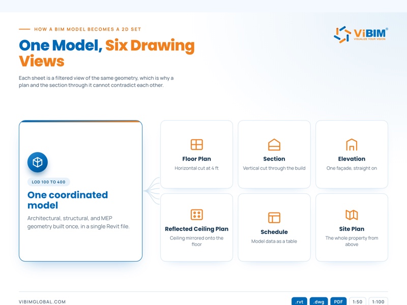
In a BIM workflow these views are not drawn separately. Each one is a filtered view of a single coordinated model, so the plan, the section, and the schedule all read from the same source data. When three views of the same room disagree with each other, they were almost certainly drawn as separate documents rather than extracted from one model.
On a topography project in the United Kingdom, ViBIM’s Revit modeling outsourcing produced the site model first and then generated the complete 2D drawing set from it as a record of existing conditions. Views extracted that way are delivered as CAD files, Revit files, or PDFs, at standard scales such as 1:50 and 1:100.
Each view type is covered in turn below, starting at the scale of the whole property and ending at the model view.
Site Plans and Plot Plans
A site plan is a view looking straight down at the whole property, showing the building footprint in relation to boundaries, access, and utilities. The sheet carries property lines, existing and proposed structures, access points, utility runs, and landscape features.
Site plans are drawn at 1″ = 20′ (1:240) or smaller so the entire parcel fits on one sheet. A plot plan covers the same ground but leans on survey data, emphasising boundaries, setbacks, and land measurements rather than building layout.
Permitting authorities usually read this pair before anything else, because site approval precedes building approval.
Floor Plans
A floor plan is a horizontal cross-section taken at 4 feet (1.2 m) above the finished floor, looking down. The view shows walls with thickness dimensions, doors and windows tagged to schedules, room names, and dimension strings. Standard plan scale is 1/4″ = 1′-0″ (1:48) in US sets and 1:50 or 1:100 in metric sets.
The floor plan is the single most referenced drawing in any construction set, and the sheet that structural, MEP, and fire protection engineers overlay their own systems onto. An error here propagates into every other discipline.
On large buildings, point cloud data often arrives in several scanning batches rather than a single handover, so plans built from discontinuous data have to be reconciled at the seams between batches before any sheet is issued.
Elevations
An elevation is a straight-on vertical view of one face of a building, drawn without perspective distortion. Every project includes four exterior elevations: North, South, East, and West. Interior elevations cover rooms with specific wall finishes, such as kitchens, bathrooms, lobbies, and conference rooms.
The elevation is where heights, proportions, and surface materials are read. Window head and sill levels, floor-to-floor dimensions, cladding changes, and roof lines all resolve on this view rather than on the plan.
One word carries two meanings on a drawing set. An elevation can be a view of a façade, and it can also be a height above a datum, so a note reading elevation 112.50 refers to a level rather than to a sheet.
Sections
A section is a view produced by cutting vertically through a building and looking at the exposed face. Section drawings reveal internal composition: floor-to-floor assemblies, wall construction layers, and structural relationships invisible in plans or elevations.
Two versions do different jobs. A building section cuts through the whole structure at 1/4″ = 1′-0″ (1:48) to show how levels stack. A wall section enlarges one slice of the envelope to 3/4″ = 1′-0″ (1:16) so the layers from foundation to roof can be counted.
Sections are the view to open when the question involves clear height, assembly thickness, or the junction where two systems meet.
Details
A detail is an enlarged view of one assembly, drawn at a scale large enough to show fasteners, material layers, and tolerances. Details are drawn at scales such as 1-1/2″ = 1′-0″ (1:8), 3″ = 1′-0″ (1:4), and full size. They carry the highest information density per square inch in the entire set.
Waterproofing failures and structural connection errors almost always trace back to missing or unclear details. The detail is where a design decision stops being a line on a plan and becomes an instruction a trade can follow.
On a heritage church project in the United Kingdom, ViBIM modelled the exterior walls as separate material layers with their own thicknesses, because a detail extracted from a single-layer wall would describe a construction that does not exist on site.
Reflected Ceiling Plans
A reflected ceiling plan is a view of the ceiling drawn as if it were mirrored onto the floor, so it reads in the same orientation as the floor plan below it. The sheet carries lighting fixtures, diffusers, sprinkler heads, access panels, and ceiling grid patterns.
Four disciplines read this one view. Architecture sets the grid, electrical places the fixtures, mechanical places the diffusers, and fire protection places the heads. That shared occupancy makes the reflected ceiling plan the earliest sheet on which a ceiling conflict becomes visible.
Schedules
A schedule is a view that presents model data as a table instead of as geometry. A door schedule lists every door by tag number with size, type, hardware set, fire rating, and frame material. A window schedule does the same for glazing assemblies, and a finish schedule maps room-by-room selections for floor, wall, and ceiling materials.
A schedule reads straight from the properties of the objects it counts, which is why it is only ever as accurate as the data embedded in the model behind it.
On a supermarket modelled for facility management in the United States, the families were built with dimensions, material information, pressure ratings, and flow rates already embedded, because the equipment schedules drawn from that model could be no better than those parameters.
Riser Diagrams and Isometric Drawings
A riser diagram is a schematic view of how a system runs vertically through a building, and an isometric drawing shows a run of pipe or duct in three dimensions on a single sheet. Neither view is a plan, and neither is bound to one floor.
The riser drops scale deliberately so that floor-to-floor order and connection sequence stay legible. The isometric holds three axes at once, so the height of a run and the direction of every turn can be read without opening a second sheet.
Both views exist to answer a question that per-floor plans cannot: where does this one line go when it leaves the floor you are looking at.
Vertical runs are also the hardest part of a building to rebuild from scan data, because each floor has to be tied back to the correct level before a riser reads as one continuous system.
3D Views and Perspectives
A 3D view is a projection taken from the model itself rather than a flat drawing, and a perspective adds vanishing points so the result reads the way the eye sees it. Both are extracted views in the same sense that a plan is, taken from the same geometry at a different camera angle.
These views are used to check spatial fit, present design options, and explain congested junctions that a 2D sheet struggles to carry. A congested plant room reads faster as one axonometric than as four coordinated plans.
A 3D view does not replace a contract drawing. The set that gets signed, sealed, and built from is still two-dimensional and drawn to scale.
The same view can appear at several points in a project, and the point at which it appears decides who produced it.
Construction Drawings by Project Phase
Shop drawings and as-built drawings are defined by when they enter the project timeline, after contract award and after construction respectively, rather than by which engineering discipline produced them. Contractors, fabricators, and field personnel produce them in response to the design drawings.
This is the axis that explains why some types of construction drawings carry no discipline prefix at all. Shop drawings come first, since they follow immediately after contract award, and as-built drawings close the sequence.
Shop Drawings
Shop drawings translate design-intent drawings into fabrication-level instructions. Contractors, subcontractors, and fabricators produce them, not the design team. This distinction defines their legal status: the design team reviews shop drawings for general conformance with design intent but does not assume responsibility for fabrication accuracy.
Design drawings say WHAT to build. Shop drawings say HOW. They include cut lists, weld symbols, bolt patterns, erection sequences, and material procurement specifications tied to a specific fabricator’s equipment and capabilities.
Common categories include structural steel connection details and piece marks, precast concrete panel layouts and embed locations, curtain wall mullion sections and anchor details, and MEP spool drawings for piping and duct section layouts.
The architect or engineer reviews each submittal and responds with one of four stamps: Approved, Approved as Noted, Revise and Resubmit, or Rejected. BIM fabrication models in tools like Tekla Structures and SysQue now generate shop drawings directly from coordinated 3D geometry, reducing the manual drafting errors that historically plagued the submittal process.

As-Built and Record Drawings
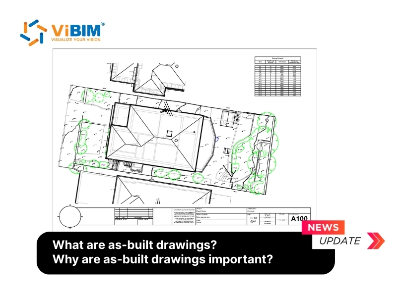
As-built and record drawings document the building as it was actually constructed, and they sit on the phase axis because they are produced after construction rather than by any single discipline. For a detailed look at as-built terminology and documentation requirements, see as-built drawings.
The two terms are not interchangeable. As-built drawings are the contractor’s field markups on printed sheets, while record drawings are the architect-verified set that folds those markups into a clean, coordinated deliverable per AIA G704.
Neither type carries a discipline prefix, which is precisely what separates them from the sheet series the design team issues.
Where no reliable record survives, the building itself becomes the source document. ViBIM processes point cloud data into disciplined Revit models, and its As-Built Scan to Modeling services generate the as-built drawing set from those models rather than from field redlines.

Construction Drawing Status From Design to Record
Drawing status is the stamp in the title block that states what a printed set is approved for, and it changes as the same drawings move through the project. This is the one axis where the drawing itself can stay identical while its meaning changes completely.
Floor plan A-101 can be issued half a dozen times over the life of a project. The geometry may not shift at all between issues, but what the sheet may lawfully be used for changes every time it is reissued.
Status describes the standing of a printed set. Schematic Design, Design Development, and Construction Documents describe how far the design itself has progressed, which is a separate question from what the current print is cleared for.
Issued for Construction, abbreviated IFC, is the decisive stamp in the sequence. It is the point at which the design team releases the drawings to be built from, and it fixes the baseline against which every subsequent change order is measured. A sheet stamped Not for Construction may carry identical geometry and still cannot be built from.
A conformed set is the term most people have heard and few can define. Once a project has been awarded and addenda and change orders have accumulated, the design team folds all of them back into the drawings and reissues one clean set, so the field reads a single document instead of a drawing plus a stack of amendments.
The status sequence is summarized below.
| Status | What the stamp says | Issued by | Approved for | Not to be used for |
| Design / Preliminary | Preliminary, Not for Construction | Design team | internal review, client sign-off | pricing, permit, construction |
| Tender / Bid | For Tender, For Bid | Design team | pricing and contractor selection | construction |
| Permit | For Permit, For Approval | Design team | authority review and permit issue | construction, unless separately stamped |
| Issued for Construction | Issued for Construction, IFC | Design team | building the work | pricing an earlier scope |
| Conformed | Conformed Set | Design team | construction with all addenda incorporated | tracing the original bid scope |
| Record | Record Drawings, As-Built | Contractor and design team at closeout | handover, operation, future renovation | construction of new work |
Each of these types of construction drawing carries the same geometry and a different legal weight, which is why the stamp is read before the linework.
The record set that closes the sequence is the one missing from a great many older buildings, or present but no longer matching what was built. That gap is what makes the next question a practical one.
How Are Construction Drawings Created?
Construction drawings are produced through three methods: hand drafting, 2D CAD, and Building Information Modeling (BIM), with BIM now the standard for new construction across the US, UK, Scandinavia, and Singapore.
For existing-building documentation, a scan to bim workflow adds reality capture before model-based drawing production begins.
Hand drafting on vellum or mylar dominated through the 1980s. Every line was ink on film. Revisions meant erasing and redrawing. The process demanded precision but offered zero coordination automation.
2D CAD software (AutoCAD, MicroStation) digitized drafting starting in the late 1980s. Revisions became faster. Copies became instant. But a floor plan, a section, and a detail were three separate files. Change one, and you updated the others manually.
Building Information Modeling shifted the process. Software like Revit, ArchiCAD, and Vectorworks builds a coordinated 3D model first, and drawings become filtered views of that model. Move a wall, and every plan, section, elevation, and detail that shows that wall updates automatically.
Quantity takeoffs, 4D scheduling, and 5D cost estimation layer directly onto the model geometry. The model is the single source of truth.
For existing buildings in renovation, adaptive reuse, and facility management, original construction plans may not exist or may not reflect decades of modifications. 3D laser scanning captures current conditions as a dense point cloud.
BIM modelers then convert that point cloud into a Revit model capable of generating any of the types of drawings in construction discussed in this guide. The 2D drawing extraction that turns that model into issue-ready sheets is exactly what our as-built drawing services deliver. This Scan to BIM workflow bridges the documentation gap between new construction and the existing built environment.
How to Read Construction Drawings
All types of construction drawings are read through the same five elements: the title block, the drawing scale, the symbol legend, the dimension system, and cross-reference navigation between sheets.
The title block sits in the lower-right corner of every sheet. It identifies the project name, sheet number, drawing title, scale, issue date, revision history, and the seal of the licensed professional responsible. Read the title block first: it tells you which discipline, which version, and who takes professional responsibility.
Scale determines how drawn dimensions translate to real-world measurements. Always check the graphic scale bar printed on the sheet, because printed copies and PDF screens may not reproduce at the original size, which makes numeric ratios unreliable.
| View Type | US Scale | Metric Equivalent | Typical Use |
| Floor plan | 1/4″ = 1′-0″ | 1:48 | Room layouts, walls, doors, dimensions |
| Site plan | 1″ = 20′ | 1:240 | Property boundaries, grading, utilities |
| Building section | 1/4″ = 1′-0″ | 1:48 | Floor-to-floor assemblies, vertical relationships |
| Wall section | 3/4″ = 1′-0″ | 1:16 | Exterior wall layers, foundation-to-roof |
| Detail | 1-1/2″ = 1′-0″ | 1:8 | Material connections, fasteners, tolerances |
| Civil grading | 1″ = 30′ | 1:360 | Contour lines, drainage, elevation benchmarks |
Standard symbols follow the conventions collected in the US National CAD Standard, and they represent door swings, window types, section cut marks, elevation tags, detail callouts, and material hatching patterns. Most projects include a legend sheet, typically G-001 or A-001, that defines project-specific symbols.
Dimensions in US construction use feet and inches. Metric projects use millimeters. Dimension strings read from outside to inside: overall building dimension first, then grid-to-grid spacing, then individual element dimensions.
Cross-references link views across sheets. A section mark on floor plan A-101 labeled “3/A-301” means section number 3 is drawn on sheet A-301. Following these references lets you navigate a construction drawing set from a plan view to the detailed view of any component without searching sheet by sheet.
One more layer sits on top of all five, and it is the one that stops most people reading a drawing set for the first time.
Common Abbreviations on Construction Drawings
Construction drawings compress repeated notes into a standard set of abbreviations, most of which are defined in the terms and abbreviations module of the US National CAD Standard. A sheet has finite area and some notes recur hundreds of times, so the abbreviation is a space decision before it is a convention.
The complication is that a handful of abbreviations shift meaning by discipline and by region. TOC reads as top of concrete on a structural sheet and top of curb on a civil sheet. CRS is read as centres in British practice and as courses in masonry notes. Project-specific abbreviations such as FCD or ISD appear with no industry-wide meaning at all.
For that reason the legend sheet of the project in hand always outranks any general list, including this one. Read the legend first, then use the table as a fallback.
The abbreviations that appear most often on a drawing set are listed below.
| Abbreviation | Meaning | Where you usually see it |
| TYP | Typical, applies to all similar conditions | plans and details, next to one dimensioned instance |
| SIM | Similar, same condition with minor variation | detail callouts |
| NIC | Not in contract | plans, marking scope excluded from the contract |
| NTS | Not to scale | details and diagrams that carry no scale |
| UON / UNO | Unless otherwise noted | general notes |
| VIF | Verify in field | renovation drawings and existing conditions |
| EQ | Equal spacing between marked points | dimension strings |
| OC | On center, spacing measured centre to centre | framing plans, stud and joist layouts |
| CLR | Clear, the unobstructed dimension | structural and MEP clearances |
| RO | Rough opening | door and window schedules |
| AFF | Above finished floor | elevations of switches, outlets, fixtures |
| FFL | Finished floor level | sections and elevations |
| EL | Elevation, a height above datum | site and building sections |
| TOS | Top of steel | structural framing plans |
| TOC | Top of concrete, or top of curb on civil sheets | structural and civil plans |
| TOF | Top of footing | foundation plans |
| BOP | Bottom of pipe | plumbing and drainage runs |
| IL | Invert level, the inside bottom of a pipe | drainage plans, British practice |
| CB | Catch basin | civil and site drainage plans |
| C/W | Complete with | specification notes, British practice |
| CRS | Centres in British practice, courses in masonry notes | framing and masonry notes |
| CL | Centre line | grids, roads, symmetrical elements |
| DIA | Diameter | pipe, duct, and reinforcement callouts |
| CONC | Concrete | material callouts |
| REINF | Reinforcement | structural details |
| GYP BD | Gypsum board | wall type assemblies |
| CMU | Concrete masonry unit | wall types and material hatching |
| GALV | Galvanized | steel and metalwork notes |
| IFC | Issued for construction | title blocks and revision tables |
Frequently Asked Questions About Construction Drawings
Six questions come up repeatedly once the four axes are clear, and they cover reading order, authorship, terminology, sheet size, and the case where no drawings survive at all.
Which construction drawing should you look at first?
Read the title block first, then the sheet index, then the site plan, and only then the floor plan of the level you care about. The title block confirms you are holding the current version of the right project, the sheet index tells you what else exists, and the site plan puts the building on the ground before you step inside it.
People who open a set of blueprints at the floor plan tend to miss the revision that made their sheet obsolete.
Which sheet is the most common drawing in a construction set?
The floor plan. Of all the types of drawings in construction, it is the most referenced sheet in any set and the one every other discipline overlays its own work onto. In an architectural set it usually carries the number A-101, which is why that particular sheet number is recognised across the industry and often appears in training material as the default example.
Who produces construction drawings?
The design team draws them, discipline by discipline, but the licensed professional who signs and seals each sheet is the one legally responsible for its content. Architects seal the A-series, structural engineers seal the S-series, and the MEP engineers seal their own. Drafters, BIM modelers, and outsourced modeling teams may do the production work, and none of that transfers professional liability. The seal does.
What are working drawings?
Working drawings are one half of the Construction Documents, and the specifications are the other half. The drawings answer how much, where, and what shape. The specifications answer how good, to which standard, and installed by whom. Neither half is complete on its own. The types of working drawings in a set are simply the discipline series, because every sheet the design team issues is a working drawing.
Where the two disagree, most contracts name which one governs, which is why an estimator reads them side by side rather than one after the other.
What size are construction drawings?
Most types of construction plans in a US set print at 24 × 36 in, known as ARCH D, with 18 × 24 in (ARCH C), 30 × 42 in (ARCH E1), and 36 × 48 in (ARCH E) used as project size demands. Larger sheets carry more information per page and need fewer cross-references between sheets.
Sheet size is also why the graphic scale bar matters more than the printed ratio. A set printed at half size still reads correctly against its own scale bar, and every numeric ratio on it is wrong.
What happens when an existing building has no construction drawings?
The building has to be measured before it can be documented, and the current method is 3D laser scanning followed by model-based drawing extraction. Scanners capture the structure as a point cloud, modelers rebuild it as a coordinated Revit model, and the drawing set is generated from that model instead of from measurements taken by hand.
ViBIM runs two independent QC passes on that model before any of the types of construction drawings are issued from it, because every drawing extracted afterwards inherits whatever the model got wrong.
Conclusion
A drawing set stops being intimidating at the point you can name where a sheet sits in it. Discipline narrows a sheet to one of the seven construction disciplines and its series, view narrows it to one kind of sheet inside that series, phase says whether the design team or a contractor produced it, and status says whether you may build from it.
Most coordination failures trace back to one of those four going unstated. A team can hold the right geometry at the wrong status, or the right status on a sheet from the wrong phase, and neither mistake is visible from the linework alone. That is the practical argument for sorting the different types of construction drawings and their purposes by axis rather than by list.
BIM workflows continue to consolidate what were once separate 2D documents into coordinated views of a single model. The shift from sheets to models hasn’t eliminated the need for construction drawings. It has made them more accurate, more connected, and easier to maintain across a project’s lifecycle.
ViBIM
Address: 10th floor, CIT Building, No 6, Alley 15, Duy Tan street, Cau Giay ward, Hanoi, Vietnam
Phone: +84 944 798 298
Email: info@vibim.com.vn