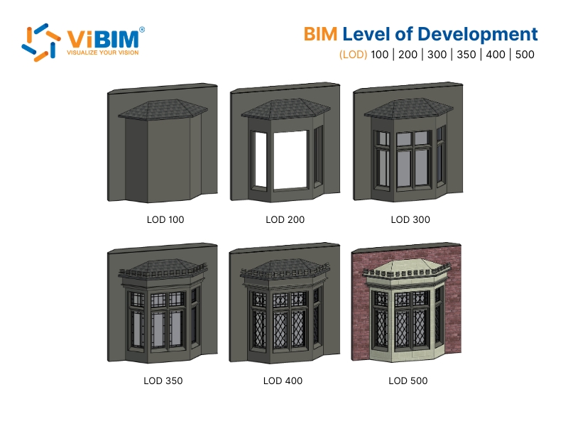
BIM Level of Development (LOD) is an industry-standard specification that lets architecture, engineering, and construction (AEC) professionals define how much detail, geometry, and information a model element carries at each stage of a project, and how far the project team can rely on it. It grades elements across six levels, from a rough placeholder at LOD 100 to an observed as-built condition at LOD 500, so each level states what an element can support.
Across those levels, LOD in BIM sets what an element can support, from massing and design to coordination, quantity take-off, fabrication, and facility operations, giving architects, engineers, and contractors one shared language for model reliability.
Reaching a stated LOD requires modeling and verification. In Revit, the view’s Detail Level changes only what appears, while the element’s geometry and information establish its LOD. On Scan to BIM work, the level also fixes how closely the model must match its point cloud. The right BIM Level of Development depends on the decision: LOD 100 supports massing, while LOD 400 supports fabrication-ready spools.
The sections below distinguish LOD from Level of Detail and Level of Information, explain the six levels and their relationship to design phases, map each level’s permitted uses, show how Revit and point-cloud quality affect delivery, and close with project benefits, ViBIM evidence, and common questions.
What Is BIM LOD (Level of Development)?
BIM Level of Development (LOD) specifies how an element’s geometry and information develop from one project stage to the next, and it gives architects, engineers, and contractors a shared way to state how far a model can be trusted at any point.
At each stage, a LOD level sets not just how much of an element has been modeled, but how far the project team may depend on it and where its limits sit. That turns a vague question like “is this model good enough to build from?” into a specific, agreed answer downstream users can act on. This shared answer is what lets LOD in BIM work as a coordination tool across design, construction, and operations, not only a modeling target.
The same door shows what “develops” means across the scale. At LOD 100 the door is only a symbol that a door exists; at LOD 300 the door carries its real width, height, material, and swing direction, accurate enough to schedule and install.
Level of Development is not the same as the BIM Maturity Levels (Level 0 to 3), which describe how advanced an organization’s BIM process is, not how reliable a single element is. The LOD framework itself rests on a documented set of industry standards.
The Origin and LOD Standards from AIA, BIMForum, and ISO
The American Institute of Architects (AIA) formalized the LOD framework in 2008, and BIMForum later expanded its practical definitions for project teams. AIA introduced the levels in the AIA E202-2008 BIM Protocol Exhibit, later updated as the AIA G202-2013 Project BIM Protocol Form, which set out LOD 100, 200, 300, 400, and 500.
BIMForum introduced LOD 350 to describe measurable interfaces with adjacent or dependent elements. Its Level of Development (LOD) Specification now ships as a definitions document plus an element-by-element spreadsheet organized by CSI Uniformat, an element-classification system.
The ISO 19650 series provides an international information-management framework, while ISO 7817-1:2024 defines Level of Information Need as the quality, quantity, and granularity of information required for a purpose. LOD 500 is not higher than LOD 400: it identifies existing or as-constructed geometry established through observation, field verification, or interpolation, with its accuracy stated or attached.
How LOD Relates to Level of Detail and Level of Information
BIM Level of Development relates to the two concepts it is most often confused with: Level of Detail, the geometry an element shows, and Level of Information, the data attached to it. A useful project shorthand is Level of Development = Level of Detail + Level of Information, although this is not a formal standards equation.
The next two sections separate each concept from BIM Level of Development.
Level of Development vs Level of Detail
The difference between BIM Level of Development and Level of Detail is that Level of Detail is an input, the amount of geometry an element shows, while Level of Development is an output, how much of that geometry and its data you can actually rely on.
Level of Detail on its own describes how much visual and graphical richness a model element carries, how closely it looks like the real thing, and it can climb without the element becoming any more dependable. A manufacturer family downloaded online can look photorealistic yet still be only LOD 200, because its size and placement have not been verified against the real project, so its Level of Detail is high while its Level of Development stays low.
The two terms share the same abbreviation, so they get mixed up often. In contracts that adopt AIA or BIMForum terminology, “LOD” means Level of Development. Searches for BIM levels of detail also commonly refer to the LOD 100 to 500 scale rather than a software display setting.
Level of Development vs Level of Information (LOI)
The difference between LOD and Level of Information (LOI) is that Level of Development states how reliably a model element, including its geometry and associated information, can be used, while LOI specifies its non-graphical data, such as manufacturer, model number, and maintenance record. Level of Detail describes the graphical input; LOI describes the data input.
An LOD 300 pipe can have measurable size, shape, location, and orientation without carrying product or maintenance data. Adding the required specification, supplier, and maintenance fields increases its information content. Field verification at LOD 500 does not automatically supply that operational data, so facility-management handover must define both the observed geometry and the required information.
What Do the LOD Levels 100 to 500 Mean?
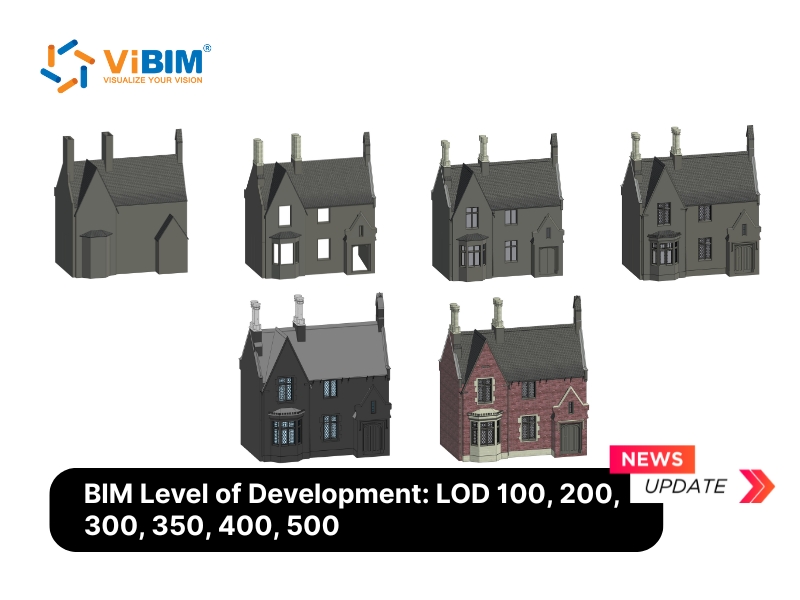
The six BIM LOD references, LOD 100, 200, 300, 350, 400, and 500, define the minimum reliability an element must reach for particular project uses. LOD 100 through 400 progressively develop design and fabrication content; LOD 500 separately records an existing or as-constructed condition and is not a higher-detail continuation of LOD 400. AIA G202 and the BIMForum LOD Specification define these expectations, so a level states more than one modeler’s judgement of how finished an element looks.
The table below gives a quick summary of each level.
| Level | Stage | What it defines (reliability) |
|---|---|---|
| LOD 100 | Conceptual | Overall mass or symbol; properties are approximate |
| LOD 200 | Schematic | Approximate size, shape, and location |
| LOD 300 | Detailed | Accurate geometry matched to design or point cloud |
| LOD 350 | Coordination | LOD 300 plus interfaces and connections |
| LOD 400 | Fabrication | Build-ready geometry and detail |
| LOD 500 | Existing/as-constructed | Geometry established from observed conditions with stated accuracy |
Each level is explained in detail below.
LOD 100 (Conceptual Design)
LOD 100 in BIM represents an element at conceptual design, drawn as a generic symbol or mass that shows only that it exists. It can support approximate area, height, volume, location, or orientation derived from the overall model, but it does not define specific element geometry.
A LOD 100 element is reliable for massing and early area or volume studies, not for measurement or coordination. It often stands in for out-of-scope items, such as neighboring structures shown as simple masses.

LOD 200 (Schematic Design)
LOD 200 in BIM represents an element at schematic design, with approximate quantity, size, shape, location, and orientation. Its geometry is generic and schematic, close enough for early spatial analysis and rough cost estimates, but not yet dimensionally accurate.
A LOD 200 element is reliable for schematic coordination and rough quantity take-off, not for exact dimensions. A typical use is a secondary or hidden element, such as a column behind a wall, modeled as a generic object at its approximate location.

LOD 300 (Detailed Design)
LOD 300 in BIM represents an element whose quantity, size, shape, location, and orientation can be measured from the model. It is sufficiently developed to convey design intent and support construction documentation and general object-level coordination.
An LOD 300 element is reliable for general coordination, clash detection, and accurate quantity take-off, but not yet for fabrication. On renovation and retrofit scopes, this level can support drawings and schedules without the added work required for fabrication detail.

What Is BIM LOD 300 in Revit?
LOD 300 in Revit means modeling each element with measurable quantity, size, shape, location, and orientation in the project’s coordinate system, using a real system or loadable family rather than a placeholder. A LOD 300 wall carries its specified core and finish layers and a measurable thickness, so it can drive construction drawings and quantity schedules.
This work commonly uses system families for walls and pipes and loadable families for fixtures and equipment, each developed to the project requirements.
LOD 350 (Construction Documentation)
LOD 350 in BIM represents an element with the measurable interfaces and connections needed for construction-level coordination. It adds adjacent or dependent relationships to LOD 300 geometry, such as supports, hangers, and joints between trades.
An LOD 350 element is reliable for detailed multi-trade coordination and installation layout, not yet for shop fabrication. In Revit, teams model explicit connection components, hangers, and supports where the scope requires them. Pipe hangers, cable-tray supports, and beam clamps then show how exposed services relate to the surrounding structure.

LOD 400 (Fabrication and Assembly)
LOD 400 in BIM represents an element with detail sufficient for fabrication, assembly, and installation. Its geometry and information can support shop drawings, manufacturing, prefabrication, and installation planning.
A LOD 400 element is reliable for fabrication, bill of materials, and spooling. It is uncommon in general Scan to BIM work and is usually reserved for fabrication-critical items, such as plant equipment or industrial retrofits that need accurate spools.

What Is LOD 400 in Revit?
LOD 400 in Revit means modeling an element with the joints, brackets, connections, and assembly detail required for shop drawings and prefabrication, using suitable families or fabrication parts. Manufacturer specifications, sizes, and installation data are included when the project scope requires them.
Some workflows develop existing design-intent families further; others replace them with fabrication parts. The agreed deliverable determines which geometry and information must change.
LOD 500 (Existing or As-Constructed Record)
LOD 500 in BIM represents an existing or as-constructed element whose geometry has been established through observation, field verification, or interpolation, with its accuracy stated or attached. It is defined by the source and verification of the geometry rather than additional fabrication detail.
An LOD 500 element does not need LOD 400 fabrication detail. It can support as-built documentation as an observed record of installed conditions; facility management and asset tracking also require the operational information defined for handover.

What Is the Difference Between LOD 300 and LOD 350?
The difference between LOD 300 and 350 is that LOD 300 defines an element on its own, while LOD 350 also defines how that element connects to everything around it. A LOD 300 pipe has the correct size and route; the same pipe at LOD 350 also shows its hangers, supports, and how it ties into nearby ducts.
The table below sets the two levels side by side:
| Feature | LOD 300 | LOD 350 |
|---|---|---|
| Primary focus | Element’s own geometry | Element plus its connections |
| Interfaces with supports and hangers | Not required by the LOD 300 definition | Measurable and coordinated |
| Revit workflow | Measurable element geometry | Plus explicit interfaces and connections |
| Scan to BIM | Geometry matched within the agreed tolerance | Plus observed interfaces where the scan captures them |
| Best used for | General coordination and QTO | Detailed cross-trade coordination |
LOD 300 and LOD 350 are the pair teams confuse most. Which level any given element sits at, though, depends less on a fixed project phase than many people expect.
Does LOD Follow the Project’s Design Phases?
No, BIM Level of Development does not strictly follow a project’s design phases, because it grades how far each individual element can be trusted rather than marking which stage the whole project has reached, so one model can hold elements at several LODs at once. The level names borrow the language of design stages, such as conceptual, schematic, and detailed, because they track how developed an element is, not because they switch on for the whole model at a milestone.
After the schematic phase, for example, most elements sit at LOD 200, yet some stay at LOD 100 while others are already modeled to LOD 300, each advanced only as far as its part of the project needs. What each of those levels actually lets a team do is set out in the capability matrix.
What You Can Rely On at Each LOD Level (Capability Matrix)
What you can rely on changes with each LOD reference: LOD 100 and 200 support massing and rough estimates, LOD 300 and 350 support measurable quantities and coordination, LOD 400 adds fabrication content, and LOD 500 records observed existing or as-constructed conditions. Just as useful is what each level cannot yet carry, which is why the level is agreed before the work rather than assumed from it.
The matrix below synthesizes the AIA and BIMForum definitions with common project uses and adapts the Approved Use Matrix published by the U.S. General Services Administration (GSA). It is a planning aid, not a replacement for a project-specific LOD specification.
| Capability | LOD 100 | LOD 200 | LOD 300 | LOD 350 | LOD 400 | LOD 500 |
|---|---|---|---|---|---|---|
| Description | Conceptual | Schematic | Detailed | Coordination | Fabrication | As-built |
| Coordination | Not dependable | Major spatial conflicts only | General object coordination | Detailed interface coordination | Fabrication and installation coordination | Reference to observed conditions |
| Quantity take-off | Approximate values derived from masses | Approximate generic quantities | Measurable specific quantities | Measurable quantities plus interfaces | Fabrication quantities | Observed quantities when included in scope |
| Cost estimation | Conceptual allowance | Generic-element estimate | Specific-assembly estimate | Coordination-informed estimate | Fabrication or committed cost | Record cost only when attached |
| 4D scheduling | Overall duration and major phasing | Major activities | Detailed assemblies | Installation interfaces | Fabrication, assembly, and means and methods | Not defined by LOD 500 unless separately required |
| Existing conditions | Overall massing | Approximate elements | Measurable observed geometry | Observed interfaces where captured | Fabrication detail where required | Existing or as-constructed geometry with stated accuracy |
Several of these uses, such as 4D scheduling and cost estimation, link each level to the wider BIM dimensions. For renovation and retrofit work that needs coordinated drawings without fabrication detail, LOD 300 often provides a practical balance between modeling effort and usefulness. Applying these levels inside Revit requires separate controls for display, element development, and verification.
How to Model LOD in Revit
To model LOD in Revit, match each element’s modeled accuracy to its target level, control how much of it shows through the view’s Detail Level, and avoid modeling anything to a higher level than the project needs. The reliability of each element comes from the geometry and data behind it, not from how much of it appears on screen.
Three steps keep LOD and view display separate.
- Control display in the view properties. Set Coarse, Medium, or Fine under
Properties > Detail Levelto change what the view shows. This setting does not establish an element’s LOD. - Develop and track the element separately. Use the system family, loadable family, or fabrication part that provides the required geometry and information. If the project’s BIM Execution Plan (BEP) tracks LOD by parameter, add the approved shared parameter through
Manage > Project Parametersand bind it to the required categories. - Verify the deliverable and stop at the agreed level. Check measurable geometry, information, interfaces, and source accuracy against the LOD matrix. Modeling to LOD 400 when the project needs LOD 300 adds hours and file weight without improving the intended use.
One of those controls, Detail Level, is regularly mistaken for LOD itself.
Level of Detail vs LOD in Revit
In Revit, Level of Detail is the view setting, Coarse, Medium, and Fine, that controls how much of each view is drawn, while LOD measures how far an element’s geometry and data can be trusted. Switching a view from Coarse to Fine changes what you see, not what the model can be relied on for; a wall set to Coarse can still be LOD 300 if its dimensions are accurate. Teams comparing BIM levels of detail across software are usually comparing Development stages, not this display setting.
Software technique is one limit on the LOD you can reach. The scan behind the model is another.
What LOD You Can Achieve from a Point Cloud Scan
The LOD in BIM you can realistically reach on a Scan to BIM project depends on the scan itself, not only the level you request, because the source data limits what can be measured and verified. A registered terrestrial scan can support LOD 300 or higher where coverage, point density, visibility, and the agreed tolerance are sufficient. Handheld or mobile scans may leave some elements below that threshold when their point density or coverage is lower.
This is why the level and capture method are agreed together. Reaching a stated LOD on reality-capture work means checking each modeled element against the available evidence: an LOD 300 wall must match the point cloud within an agreed tolerance, while LOD 500 geometry requires observation, field verification, or interpolation of the installed condition. Where the source cannot support the target, the options are supplementary measurements, a denser rescan, or a lower agreed LOD.
Key Benefits of a Clearly Defined LOD in BIM Projects
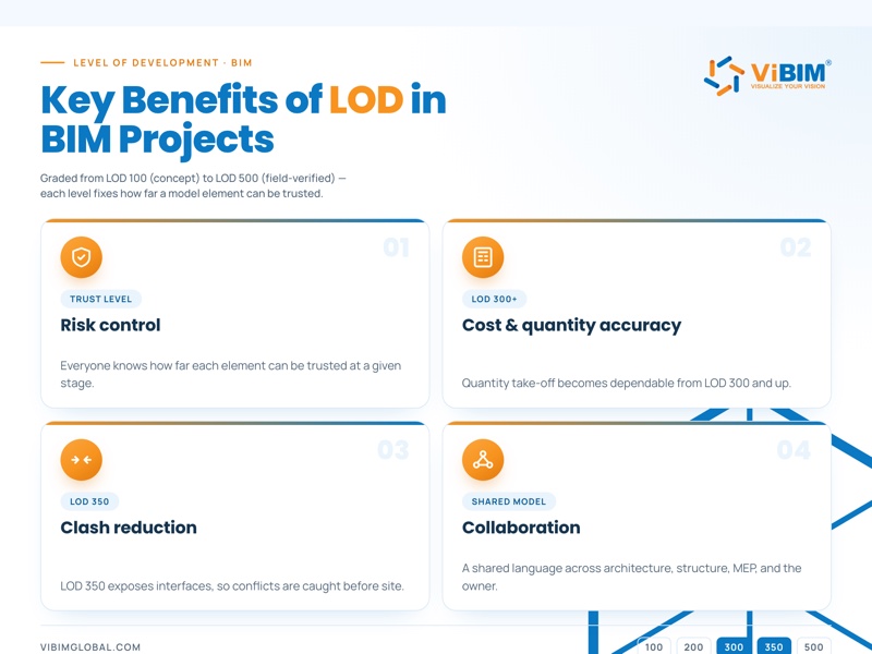
A clearly defined LOD in BIM gives a project six practical benefits: lower risk, accurate cost and quantity data, fewer on-site clashes, smoother collaboration, right-sized modeling effort, and a reliable basis for facility management. Each one comes from the same source, a shared agreement on how far every element can be trusted.
The benefits break down as follows.
- Lower risk. An LOD matrix states the permitted use of each element, so downstream teams do not treat approximate LOD 200 geometry as construction-ready.
- Accurate cost and quantity data. LOD 200 supports rough estimates; accurate quantity take-off becomes dependable when LOD 300 geometry can be measured.
- Fewer clashes. LOD 350 exposes the interfaces and connections between trades, so clashes surface before installation rather than on site.
- Smoother collaboration. LOD gives architecture, structure, MEP, and the owner one shared language, so handoffs carry less ambiguity.
- Right-sized effort. Assigning LOD by element keeps fabrication detail out of components that need only coordination, reducing modeling time and file weight.
- Reliable facility management. LOD 500 records observed installed geometry; facility teams can use it when the handover also includes the asset and maintenance information they require.
Real projects show how these requirements translate into tolerance, scope, and acceptance criteria.
How ViBIM Applies LOD on Scan to BIM Projects
ViBIM sets the LOD for each deliverable, models every element only to the level the project relies on, and verifies it against the point cloud before handover. The level changes from job to job, and so does the work behind it.
Each model is quoted against the point cloud in one of three tolerance bands, 2 in (50 mm), 1.2 in (30 mm), or 0.6 in (15 mm), so “accurate” carries a number before modeling starts. The selected LOD is one of the main variables affecting hours, file size, price, and turnaround. ViBIM therefore quotes each scope against a stated level and uses the agreed LOD table as the acceptance basis for the finished model.
Three projects show how the scope changes by level.
LOD 200, train station, Canada (6,700 m² / 72,000 sq ft). The architecture, structure, and terrain were modeled at LOD 200, schematic enough for space planning, while the railway track alignment was held to within 0.4 in (10 mm).

LOD 300, factory, US (3,800 m² / 40,900 sq ft). Dense MEP systems across six floors were modeled at LOD 300 and matched to the point cloud within 0.6 in (15 mm), providing a measurable basis for Navisworks coordination.

LOD 400, aluminum extrusion press, US (1,500 m² / 16,150 sq ft). An aluminum extrusion press and its conveyor system were taken to LOD 400, a fabrication-ready model accurate to 0.25 in (6 mm), built straight from the point cloud.

The goal is always the right level for the job, not the highest one.
Why Choose ViBIM for Point Cloud to BIM
Reliable LOD delivery comes down to process, and ViBIM has refined one across more than 1,000 Scan to BIM projects and 250,000 hours of Scan to BIM delivery since 2014. The agreed level is checked against the point cloud before delivery.
That record rests on a few fixed commitments.
- ViBIM has completed more than 1,000 projects and delivered 250,000 hours of Scan to BIM work since 2014.
- Two-layer QC checks the delivered LOD against the point cloud, and 99% of projects have been delivered on time.
- Project teams build primarily in Revit and review models in Navisworks Manage against project-specific US or UK requirements.
- New clients receive a quote within 12 to 24 hours and can request a free trial.

To scope a model at the right LOD, explore ViBIM’s Point Cloud to BIM services or send drawings for a free trial.
Frequently Asked Questions About BIM LOD
The most common BIM LOD questions concern what the specification controls, how teams apply mixed levels, and when a formal LOD is necessary. The answers below clarify those points, while the dedicated selection guide explains how to choose a level for a specific project.
What is LOD used for?
LOD in BIM is used to state how far a model element can be trusted at each stage of a project, from design and coordination to fabrication and facility operations.
What is the LOD full form in BIM?
In BIM, LOD stands for Level of Development, though the same abbreviation is often read as Level of Detail.
What does LOD mean in construction?
In construction, LOD means how complete and reliable a BIM element is for an agreed use, from LOD 100 as a rough concept to LOD 500 as observed existing or as-constructed geometry.
What is the LOD specification?
The LOD Specification is BIMForum’s element-by-element reference for defining model content at each level, organized by classification systems such as CSI Uniformat.
Can one BIM model contain multiple LOD levels?
Yes, one BIM model can contain multiple LOD levels. Each element is developed to the level required for its intended use.
How do I choose the right LOD?
Choose the LOD by the decision the model must support, matching effort to what the project actually needs. Our guide on how to choose the right LOD walks through the selection process.
Is a defined LOD required for all AEC projects?
No, a defined LOD is not required for every AEC project. A small or simple project may not need a formal LOD, but any project that relies on the model for coordination, fabrication, or handover benefits from agreeing one up front.