Point cloud to BIM turns a 3D laser scan of an existing building into a model a project team can build from: an intelligent, coordinated BIM model made from measured reality. The scan on its own is only a point cloud, millions of raw 3D points; converting those point clouds to BIM is what makes the data designable, measurable, and ready for coordination. A well-built point cloud BIM model becomes the accurate as-built basis a project relies on. It cuts rework and gives every discipline a single source of truth.
How to convert a point cloud to BIM follows a clear workflow, from scoping and cleaning the cloud to modeling by discipline and validating against the source scan. How accurate, detailed, and costly the result is depends on the LOD you set and how much you choose to model, more than on the software, though the work runs in Revit, ArchiCAD, or other BIM tools. The output supports everything from renovation design to facility management.
The sections below walk through each stage of converting a 3D point cloud to BIM, the decisions that drive quality, and where outsourcing point cloud scan to BIM fits into wider BIM modeling.

What Is Point Cloud to BIM?
Point cloud to BIM, sometimes called scan to BIM, is the process of converting millions of 3D laser-scanned data points of an existing building or structure into a detailed, intelligent, parametric BIM model. The point cloud itself is the raw output of a laser scan, a dense field of measured points, each with an X, Y, and Z coordinate and often an RGB color value, saved in formats such as RCP or E57. On its own, that point cloud data is pure geometry. You cannot select a wall, schedule a door, or run a clash check on a cloud of points, because nothing in it knows what a wall or a door is.
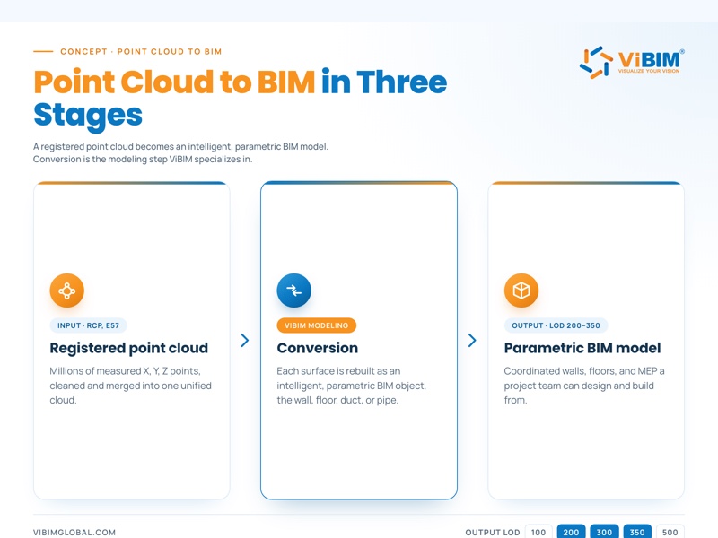
The conversion is the step that adds that intelligence. Working in BIM authoring software, a modeler uses the point cloud as a reference and rebuilds it as parametric objects, the walls, floors, ducts, and pipes that carry data such as material, dimensions, and function. The result replaces manual measurement with an accurate digital replica a project team can design, measure, and coordinate from.
The diagram below traces the path, from a 3D point cloud through conversion to a finished, data-rich model.
Point Cloud to BIM vs Scan to BIM vs a Regular BIM Model
Scan to BIM is the full pipeline, point cloud to BIM is the conversion step inside it, and a regular BIM model is an output that needs no scan at all. Point cloud to BIM and scan to BIM often get used interchangeably, and the first is also called as-built BIM modeling or reality capture to BIM. Even so, each term sits at a slightly different point in the process, and telling them apart clarifies what this guide covers.
The table below places each one:
| Term | What it is | Where it sits |
| Scan to BIM | The full end-to-end pipeline: capture, register, then model | Whole workflow |
| Point cloud to BIM | The conversion step that turns a registered cloud into model geometry and data | A stage inside scan to BIM |
| A regular BIM model | A model authored from design intent, with no scan involved | Output, can exist without any scan |
The line that matters most is the source of the geometry. Point cloud to BIM rebuilds a building from measured reality, while a regular BIM model starts from design intent and never touches a scan.
With the term pinned down, the value of doing it becomes clearer.
Key Benefits of Point Cloud to BIM
The real gain from converting a point cloud to BIM is a model you can work with: a raw scan only records points, while a BIM model can be edited, measured, and coordinated. Every benefit below traces back to that one shift, from passive measurement to an active, intelligent model.
The main benefits of making that conversion are:
- A usable model: captured reality becomes something you can query, edit, and pull quantities from, which a raw cloud cannot do.
- As-built accuracy: the model reflects the building as measured, not as the original drawings assume.
- Clash detection and coordination: modeled elements can be checked against each other before any work starts on site.
- A single source of truth: one coordinated model serves design, construction, and facility management from the same data.
- A basis for renovation and retrofit: reliable geometry to design against where the original drawings are missing or outdated.
These are the gains specific to the modeling step. For the economic impact and the wider case, see our full breakdown of the benefits.
Realizing these benefits depends entirely on how the conversion is carried out.
How Do You Convert a Point Cloud to BIM?
Converting a point cloud to BIM follows six stages, from setting the scope to delivering the finished model. It starts from a registered point cloud, the cleaned and unified scan that laser scanning and registration produce. The stages below are how we run point cloud to BIM modeling in production across more than 1,000 projects, and they apply in any BIM authoring tool. For the click-by-click version in Revit, see our guide to point cloud to Revit conversion.
- Define scope, LOD, and tolerances
- Prepare and QC the point cloud
- Set up the project and align the cloud
- Model the BIM elements, main runs first
- Validate against the source scan
- Deliver and resolve post-handover QC
What separates a clean conversion from a rough one shows up in three habits most guides skip: QC-ing the point cloud before any modeling starts, modeling the main runs before the branches, and validating the finished model against the source scan. The diagram below maps all six stages end to end.
Stage 1: Define Scope, LOD & Tolerances
Scope is fixed first: which systems to model, to what LOD and LOI, and within what tolerance. Before any modeling, the team agrees what is in and out of scope, the level of detail each element needs, and the accuracy the model has to hold. Building type shapes these choices, since a heritage façade, a hospital, and an industrial plant each carry different modeling standards. A tolerance is set here too, scaled to the LOD and the accuracy the project needs.
The common LOD targets map to different jobs:
| LOD | Typical use |
| LOD 200 | Concept and early coordination |
| LOD 300 | Design and documentation |
| LOD 350 | Coordination and clash detection |
With scope locked, the next gate is the quality of the data itself.
Stage 2: Prepare & QC the Point Cloud
The point cloud is checked for errors before any modeling starts, so no hours are wasted building on top of bad data. A quick pass over the cloud catches the issues that would otherwise surface halfway through production, when they cost far more to fix.
The check looks for three things:
- Duplicate points that inflate the file and blur geometry.
- Misaligned scan regions where separate scans do not line up.
- Coverage gaps where an area was never captured.
Anything found is reported to the client early, so the scope and schedule can be adjusted before modeling time is spent.
Once the data is clean, it has to be positioned correctly in the project.

Stage 3: Set Up the Project & Align the Cloud
The point cloud is imported into a coordinated base file set to the right units, version, and coordinate system, then aligned to its real-world position using origin-to-origin or shared coordinates. Most teams import into Revit, but any BIM authoring tool works, as the software section below covers. Getting the alignment right means every element modeled later lands in the correct place, both within the file and against the project’s survey control.
Once the cloud is imported, the team fixes the levels and grids that modeling will reference and cuts a standard set of working views: two elevations, a plan, and a 3D view. The alignment method, whether origin-to-origin or shared coordinates, follows whatever the client’s project uses.
With the cloud aligned, modeling can begin, and the order matters.
Stage 4: Model the BIM Elements, Main Runs First
BIM modeling from point cloud data works discipline by discipline, in a deliberate order: primary routes and dense zones first, then secondary branches and individual components. Starting with the busy areas, the main MEP risers, plant rooms, ceilings, and corridors, sets the spatial backbone everything else has to fit around.
From there the work moves outward to the secondary branches and the sparser zones, then to individual components built as reusable families. Each family is cleaned up, with its geometry and materials sorted, before it goes into the live model, which keeps the file consistent and quick to coordinate. Across all of it, the model is split by discipline, architecture, structure, and MEP, so each can be checked and delivered on its own.
This main-runs-first order is not arbitrary. It mirrors how the building constrains its own spaces, and it stops later elements from being modeled into positions the primary systems will not allow.
A completed model still has to be proven against the reality it came from.

Stage 5: Validate Against the Source Scan
The finished model is checked back against the scan in two independent layers, confirming it matches reality within the agreed tolerance. Validation is treated as its own stage, not a glance at the end, because an unchecked model can drift from the data it was built on.
The two layers run as follows:
- Section checks: longitudinal and cross sections are cut through the model and compared against the cloud to verify geometry line by line.
- Clash and coverage review: a pass in Navisworks finds missing or extra elements and runs a deviation check against the source cloud.
Because the two layers are independent, an error that slips past one is caught by the other.
Once validated, the model is ready to hand over.

Stage 6: Deliver & Resolve Post-Handover QC
The validated model is handed over through an agreed channel, and any client QC feedback is resolved within the original scope before close-out. Delivery runs over a secure route such as FTP, Box, Google Drive, or ACC, in whatever formats the project calls for.
After handover, in-scope corrections are made as part of the job. In our experience most post-handover feedback is minor geometry tweaks, handled inside the original scope; anything larger is re-scoped clearly rather than absorbed, and recurring issues are logged to sharpen the next project.
How well each stage is executed is exactly what decides the model’s accuracy, detail, and cost.
What Determines the Accuracy, LOD & Cost?
Three factors decide how accurate, detailed, and costly a point cloud to BIM conversion is: the LOD and LOI you set, the tolerance you need, and how much you model versus leave as reference data. None of them is about the software. They are scoping decisions made before modeling starts, and they are where most of a project’s budget is won or lost. Get them right and the project is scoped sensibly; get them wrong and you either pay for detail no one uses or find the model is not accurate enough.
For a full breakdown of what LOD is and each tier, see our dedicated guide.
The first of the three is how much detail the model is built to.
How LOD and LOI Shape Scope and Effort
The higher the LOD and LOI, the more detail and embedded data each object carries, and the more hours the model takes to build. LOD covers how much geometric detail an element holds; LOI covers the non-geometric data attached to it, such as manufacturer, material, or maintenance information. Pushing both up adds real cost, so the right move is to match the level to the purpose rather than defaulting to the highest.
The effort climbs with each tier:
| LOD | What it adds | More effort because |
| LOD 200 | Generic placeholders | Few elements, low detail |
| LOD 300 | Accurate, specific geometry | Every element measured and placed |
| LOD 350 | Connections and interfaces | Element-to-element detail |
| LOD 400 | Fabrication and assembly detail | Shop-level modeling |
A model built for early coordination rarely needs LOD 400, and paying for it wastes budget.
Detail aside, the model is only as good as the accuracy it is held to.
What Drives Accuracy and Tolerance
Three things upstream of modeling set the accuracy of the result: scan quality, registration, and the tolerance the scope defines, not the authoring tool. A model can only ever be as accurate as the data it is built from. No amount of careful modeling recovers detail a sparse or noisy scan never captured.
Accuracy is set by three inputs:
- Scan density and quality: how finely and cleanly the site was captured.
- Registration: how precisely the separate scans were aligned into one cloud during point cloud registration.
- Tolerance band: the deviation the scope allows, which the LOD and the required accuracy determine.
This is why a careful provider ties accuracy to the data and the scope, not to a promise about the software.
The last lever is the biggest cost decision: what to model at all.
What to Model vs Carry as Reference Data
You do not model everything: elements that inform design or coordination get modeled, while complex or low-value geometry stays linked as point cloud reference. This single decision moves cost and timeline more than any other, because modeling time scales with the number and intricacy of the objects built.
A workable split looks like this:
- Model it when the element drives design or coordination: structure, the main MEP runs, and the building envelope.
- Keep it as reference when the geometry is complex but low-value: ornate moldings, decorative detail, anything that does not inform a decision.
Leaving intricate, non-critical geometry as a linked cloud gives the design team the visual context without the cost of modeling every curve.
These decisions play out in whatever software the team uses to build the model.
Which Software Is Used for Point Cloud to BIM?
The main software for point cloud to BIM is Autodesk Revit, the most widely used BIM authoring tool, supported by ArchiCAD, Navisworks, and ReCap Pro. No single program does the whole job, so the work runs across a few tools that connect to each other, each covering one part of the conversion.
The common tools and their roles:
| Tool | Role |
| Revit | BIM authoring, most widely used; links point clouds natively (.RCP) |
| ArchiCAD | BIM authoring alternative |
| Navisworks | Coordination, clash, and deviation review |
| ReCap Pro | Point cloud processing and preparation |
| EdgeWise and scan-to-BIM plugins | Semi-automatic surface extraction and point cloud segmentation |
Revit is the default for most teams, but it is one option among several, not a requirement. For a comparison of the options, see our guide to the best scan to BIM software.
Whatever the tool, the output serves the same real-world uses.
Applications of Point Cloud to BIM
Point cloud to BIM is used across the building lifecycle: as-built documentation, renovation and retrofit design, construction verification, facility management, and heritage conservation. In each case the value is the same, a reliable model of what is actually there, but the use it is put to changes.
The most common applications are:
| Application | What it enables |
| As-built documentation | An accurate record of existing conditions |
| Renovation and retrofit design | Designing against real geometry, not old drawings |
| Construction verification | Comparing built work against the design for quality assurance |
| Facility management | Feeding asset and space data into operations |
| Heritage and conservation | Digitizing complex existing structures without contact |
These uses span new and old buildings alike, wherever an accurate digital record matters.
Delivering these outcomes reliably takes an experienced conversion partner.
Point Cloud to BIM Services at ViBIM
ViBIM converts point cloud data into coordinated BIM models for survey and AEC firms, with two independent QC layers, a 99% on-time delivery record, and turnaround up to 30% faster than the market average. We focus on the point cloud to BIM conversion itself, the modeling that turns a registered cloud into an accurate, intelligent model and part of our broader 3D BIM modeling services, for clients across the US, UK, Canada, Australia, and the EU.
That expertise rests on a specific track record:
- A decade of specialist work: more than 1,000 projects and over 250,000 hours of scan to BIM delivered since 2014.
- Qualified modelers: a team of 30+ modelers, each holding a degree in Architecture or Civil Engineering.
- Standards-aligned QC: two independent quality layers built around ISO 19650, PAS 1192, and the BIM Forum LOD Specification.
- Industry contribution: our founder helped author Vietnam’s first national BIM guidelines, having pioneered BIM in the country since 2011.
- Purpose-built tooling: in-house Revit API and Dynamo automation developed specifically for point cloud to BIM conversion.
Handing the modeling to a dedicated team keeps it accurate and on schedule while your own people stay on design and delivery. If you have a point cloud ready or a project to scope, our point cloud to BIM services team can take it from raw data to delivered model. Contact us to scope yours, or start with a free trial to see the quality first.

Frequently Asked Questions
Is point cloud to BIM the same as scan to BIM?
Mostly yes, the two terms are used interchangeably. The one nuance: point cloud to BIM refers specifically to the modeling step that converts a registered point cloud into a BIM model, while scan to BIM can describe the whole process from on-site capture onward.
Can you convert a point cloud to BIM automatically?
Partly. Scan to BIM automation with the Revit API and Dynamo speeds up repetitive modeling and some checks, but interpreting the cloud, modeling by discipline, and QC still need an experienced modeler. Full automation is not yet reliable for production work.
What file formats are used for point cloud to BIM?
Common inputs are RCP, E57, PTS, and LAS, and common outputs are RVT (Revit), IFC, and DWG. The right pairing depends on the software each party uses and what the deliverable has to support; for a full rundown, see our guide to point cloud file formats.
How accurate is a point cloud to BIM model?
Accuracy depends on the scan quality and registration, so a careful provider will not promise a fixed figure up front. The model is built to the LOD and tolerance each scope defines, then validated with a deviation check against the source scan to confirm it holds.