As-built drawings are the final set of construction documents that record how a building was actually built, including every change made during construction. Contractors mark these changes on the construction set as the work proceeds, which is why the profession also calls them red-line drawings, or record drawings once a design team formalizes them. Where the original design shows what was intended, the record shows what actually exists.
A complete as-built set contains six component categories, from building layout and structure through to interior finishes and specifications, and it is produced through a five-step workflow that turns an on-site laser scan into coordinated models and drawings. The sections below explain which changes a set records, who creates it, why it matters across a building’s lifecycle, how to raise its quality, and how it differs from formal record drawings. For building owners and facility managers, the accuracy of that documentation decides how confidently they can maintain, permit, and renovate a building for decades.
Producing that accuracy from raw site data is exactly the Scan to BIM work ViBIM has delivered across 1,000+ projects since 2014.
What Are As-Built Drawings?
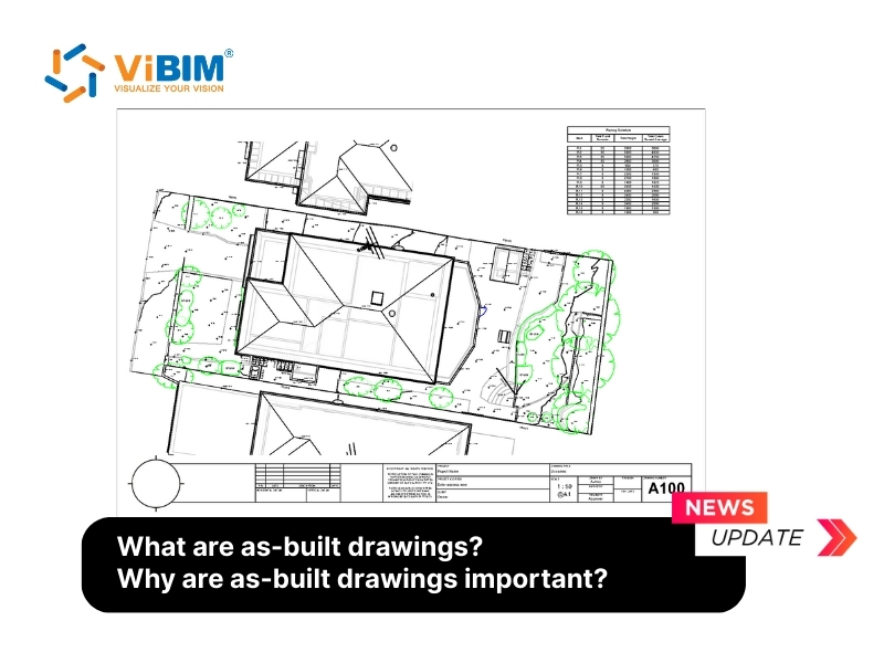
As-built drawings are revised construction documents that show the exact dimensions, geometry, and location of everything actually installed on a project. The contractor submits this marked-up set at completion, so the drawings represent the finished building rather than the original design intent.
The same documents go by several names. Professionals call them record drawings, red-line drawings, or as-built plans, and each term points to the same core idea: a verified record of what was built. The “red-line” name comes from the red ink contractors use to mark changes directly on the construction set.
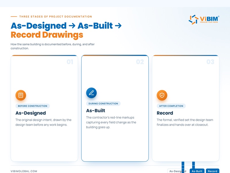
Three related document types describe a building at different stages, shown below:
- As-designed drawings show the original project intent before construction begins.
- As-built drawings capture the field changes made during construction, usually as red-line markups.
- As-constructed drawings, also called record drawings, are the final, professionally formatted documents delivered to the owner.
The American Institute of Architects (AIA) is precise about these terms. Its B101 agreement distinguishes as-designed record drawings, the architect’s full design record including addenda, ASIs, change orders, and construction change directives, from as-constructed record drawings, “commonly called ‘As-builts,'” which record the project as built from the contractor’s mark-ups. Because that set derives from contractor-furnished information, the AIA holds that the architect is not responsible for its accuracy, which is exactly why responsibility for the final record should be spelled out in the contract.
The RIBA Plan of Work 2020 defines “as-constructed” information as documentation that represents what has actually been built, assembled from specialist subcontractor records and final construction-issue documents and handed over at project close-out. This information becomes the reference every downstream team relies on once the project team disperses.
What Changes Do As-Built Drawings Capture?
As-built drawings capture every change that moves the finished building away from the original construction documents, from minor field adjustments to formally approved design revisions. Some changes are small enough to correct on the spot; others are significant enough to require a paper trail.
Field crews handle the first group directly. A relocated outlet, a duct rerouted around an unexpected obstruction, or a slightly repositioned wall gets red-lined as work proceeds. The second group carries documentation because a formal instrument authorized it. The changes that typically appear on as-built drawings are listed below:
- Change orders that alter the scope, cost, or schedule of the work.
- Requests for Information (RFIs) whose answers change how something is built.
- Construction Change Directives (CCDs) issued to keep work moving before pricing is settled.
- Architect’s Supplemental Instructions (ASIs) that clarify or adjust the design.
- Value-engineering and constructability decisions that substitute materials or methods in the field.
Each recorded change is a deviation from the design, and tracking these variances is the entire point of an as-built set. Under AIA A201 Section 3.11, the contractor is obligated to maintain a record of these field changes throughout construction, not reconstruct them afterward.
On an existing building, many of these deviations were never written down at all, which is where laser scanning becomes decisive. A scan exposes the real, current condition instead of trusting a decades-old drawing. On one dense MEP retrofit for a US industrial facility, the mechanical, electrical, and plumbing systems had drifted well beyond the original layout; ViBIM modeled the as-built condition to LOD 300 straight from the point cloud and flagged system clashes in Navisworks before any drawing reached the client.
A scan only becomes a drawing set after someone decides what counts as built and to what tolerance. ViBIM’s Scan to BIM modeling services take registered RCP, RCS, or E57 data and return native Revit objects across architecture, structure, and MEP at LOD 100 to 500, with two independent QC layers before any sheet is extracted.
Components of a Complete As-Built Set
A complete as-built set contains six component categories that together define the constructed asset, from its structural frame to interior finishes and specifications. These categories capture both visible elements (building layout, design features) and hidden systems (MEP, utilities), each recorded as it was actually built rather than as it was designed.
An as-built package spans the same disciplines as the original construction documents: architectural, structural, MEP, and civil or site drawings, plus low-voltage systems such as security and fire alarm. Each discipline carries its own as-built floor plans, sections, and elevations. For the full taxonomy of drawing types across a project, see our guide to the types of construction drawings.
The table below breaks down each component, its contents, and documentation purpose:
| As-Built Component | Description | Documentation Purpose |
| Building Layout and Structure | Floor plans, elevations, structural elements including beams, columns, foundations, and load-bearing walls | Defines the physical framework and spatial relationships |
| Design Features | Architectural details including doors, windows, partition walls, staircases, and lighting arrangements | Documents interior configuration and circulation patterns |
| Mechanical Systems | Diagrams and data for HVAC equipment, plumbing networks, and electrical distribution grids | Supports operational functionality and maintenance planning |
| Utilities | Critical connections and hardware for water supply, sewage lines, gas pipes, and main power feeds | Enables emergency response and system modifications |
| Interior Finishes | Materials selected for flooring surfaces, wall treatments, custom cabinetry, and specific fixture types | Records aesthetic specifications and replacement requirements |
| Specifications | Exact materials used, final measurements, installation methods, testing protocols, and scaled dimensions | Provides technical reference for future work |
Standard Notation Conventions
Standard notation conventions in as-built drawings include revision clouds, delta symbols, annotations, revision blocks, and reference numbers. Drafters apply these five markings to track modifications and make visual identification immediate for reviewers.
- Revision clouds are freeform, cloud-shaped outlines that circle modified sections on drawings. These irregular boundaries draw attention to specific areas where changes occurred, making it easy for reviewers to spot alterations without reading every dimension.
- Delta symbols use a triangular character placed next to a modified element. This convention flags a difference between the original bid set and the final constructed result. Some organizations use sequential numbers inside the delta to track revision history.
- Annotations provide the textual context that explains an alteration. Notes may include the date of the change, the technical reasoning behind it, or a reference to the authorizing document such as an RFI response or change order.
- Revision blocks are dedicated table areas near the drawing margin. These blocks hold administrative details including modification descriptions, responsible parties, and approval timelines, creating a formal audit trail for the documentation.
- Reference numbers are unique numeric identifiers linking every change to external documentation. They connect a drawing modification to approved change orders, RFI responses, or submittal logs held in the project files.
Who Creates As-Built Drawings?
Four parties create as-built drawings, each responsible for a different layer of accuracy:
- General contractors mark field changes in real time, red-lining the construction set as modifications happen on site.
- Architects finalize the documentation, folding raw field data and red-line markups into clean digital files. The Architect’s Handbook of Professional Practice defines record drawings as documents “revised to reflect and represent the actual conditions of the project as it was constructed, usually based on marked-up prints, drawings, and other data furnished by the contractor to the architect,” and notes the term is preferable to “as-built drawings.”
- Survey companies and laser-scanning firms capture existing conditions as a dense point cloud, the foundation for accurate 3D modeling. On the office side, drafters translate field notes, scans, and markups into clean sheets teams can use for planning and permitting.
- BIM specialists convert that point cloud into coordinated Revit models across architectural, structural, and MEP disciplines.
The last step is where ViBIM works. The as-built BIM modeling stage interprets dense scan data and rebuilds it as accurate native BIM objects, a skill distinct from field scanning: scanning professionals focus on capture quality, while modelers focus on coordination and object creation. On a complex project, the finished set passes through all four roles in sequence.
Why As-Built Documentation Matters
As-built documentation serves four operational purposes across a building’s lifecycle: onboarding efficiency, facility maintenance, permit approval, and future renovation planning. Beyond daily operations, they also carry legal and contractual weight that owners rely on long after handover.
- Onboarding efficiency improves when new team members reach verified documentation immediately. Subcontractors start work faster without hunting for outdated specifications or missing files during handover, which shortens the learning curve for maintenance staff inheriting an unfamiliar facility.
- Facility maintenance becomes far more effective when crews can locate hidden systems quickly. Accurate documentation pinpoints buried utilities, concealed junction boxes, and modified duct runs, so teams cut long-term operational costs by removing guesswork during emergency repairs.
- Permit approval depends on accurate as-built documentation in many jurisdictions. Building departments often require the final as-built plans before issuing a Certificate of Occupancy, and inspectors verify code compliance by comparing documented changes against the original submissions. Occupancy delays frequently trace back to incomplete or inaccurate as-built plans submitted at close-out.
- Future renovations benefit from a documented change history. Architects analyze structural modifications to plan retrofits accurately, and investors avoid expensive exploratory demolition by knowing exactly what sits behind the walls before design begins.
The stakes are more than operational. As-built drawings are a contractually binding deliverable under AIA A201, and owners use them to settle insurance or legal questions, to lease space, and to sell or refinance a property. Poor documentation also carries a measurable cost: construction rework studies have put the direct cost of rework at roughly 5% of contract value, and higher once indirect costs are counted, with inadequate documentation and late design changes among the leading causes.
Stephen R. Pettee, CCM, put the long-term value plainly in a Construction Management Association of America paper: “They are important for those who use the finished product, as they provide a legacy of what was actually built. This legacy becomes more important, as we continue to build on top of old work, land ownership changes, or for public works, as employees familiar with what was built are replaced over time by attrition.”
How As-Built Drawings Are Created
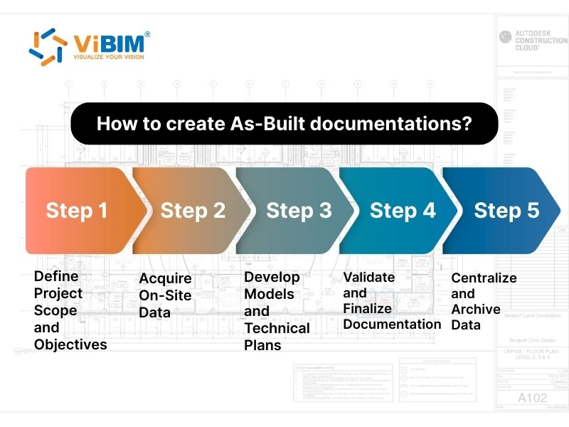
Creating as-built documentation follows a five-step workflow: define scope, acquire data, develop models, validate accuracy, and archive records. The timeline and deliverables shift with project complexity, but the sequence holds across projects, and modern as-built work increasingly runs on laser scanning and BIM rather than manual measurement.
The steps below walk through the full workflow from planning to final archive:
Step 1: Define Project Scope and Objectives
Project managers must clarify documentation requirements before site work begins. Different goals require different levels of detail: a simple renovation may need a basic drawing set, while a complex retrofit demands comprehensive BIM models with full MEP coordination.
- Level of Development (LOD) specifications determine modeling detail. LOD 100 provides basic spatial representation, LOD 200 adds approximate geometry, LOD 300 includes precise dimensions suitable for coordination, and LOD 400 provides fabrication-ready detail with exact sizes and connections.
- Deliverable formats should be specified upfront. Common outputs include Revit native files (RVT), Industry Foundation Classes (IFC) for interoperability, AutoCAD drawings (DWG) for 2D documentation, and PDF exports for distribution.
- Accuracy requirements depend on intended use. Facility management typically accepts tolerances of 5 to 10mm, renovation planning may require 3 to 5mm, and MEP coordination often demands tighter tolerances to guarantee clearances.
Step 2: Acquire On-Site Data
Survey teams capture existing site conditions to document every modification from the original layout. Two primary methods exist: traditional manual measurement and laser scanning.
- Traditional measurement uses tape measures and total stations. This approach works for small spaces but consumes significant time on larger projects, introduces human error, and requires physical return trips to revisit the site.
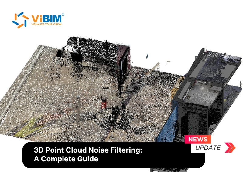
- Laser scanning has become the industry standard for as-built data capture. It records millions of data points that form the foundation for accurate BIM modeling, and scan quality directly drives model accuracy: poorly registered scans or coverage gaps create problems downstream. Survey teams deliver registered point cloud files in formats like Autodesk ReCap (RCP/RCS) or E57, which BIM specialists use as reference data. Manufacturer specifications typically claim 1 to 3mm accuracy at distances up to 100 meters (328 feet), though environmental conditions affect real-world results.
The investment in quality scan data pays off throughout the project. Teams can revisit the data digitally without returning to the physical site, and the registered point cloud becomes the single reference every discipline models against.
Step 3: Develop Models and Technical Plans
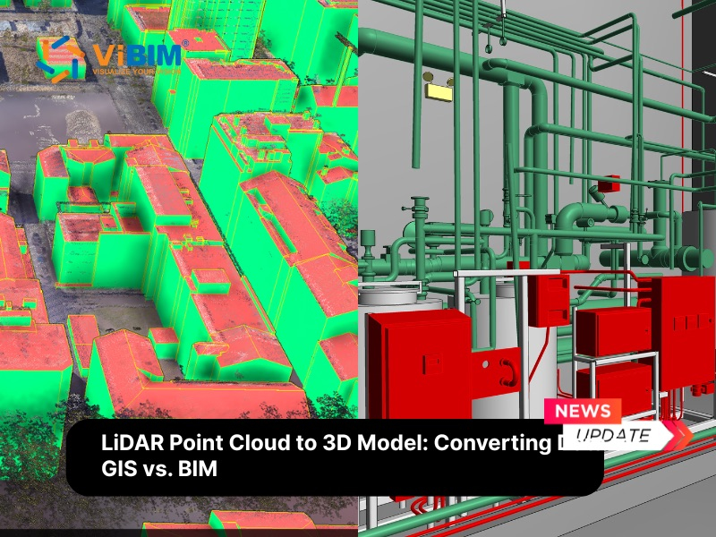
BIM specialists develop precise 3D models from the collected point cloud data once scanning concludes. The point cloud to BIM process transforms dense scan information into native BIM objects that carry geometric and parametric data.
Modeling Challenges and Solutions:
Point cloud data presents real interpretation challenges. Occluded areas, the spaces blocked from the scanner’s view, require professional judgment to model accurately. Experienced modelers recognize scan shadows behind equipment, inside wall cavities, and above ceiling systems, and they close those gaps with industry knowledge instead of fabricating information. Material identification from grayscale point clouds demands the same expertise: modelers distinguish concrete from masonry, steel from aluminum framing, and one MEP system type from another based on shape, size, and routing.
Discipline-Specific Modeling:
- Architectural modeling documents walls, doors, windows, ceilings, and spatial layouts, tracing point cloud data to place elements at their true locations and define room boundaries for area calculations.
- Structural modeling captures beams, columns, foundations, and load-bearing elements, representing steel connections and concrete members accurately enough for renovation engineering analysis.
- MEP modeling maps mechanical, electrical, and plumbing systems, which deviate most from the original design because of field conditions and coordination conflicts. Pipe sizing, duct dimensions, and conduit routing must match the point cloud evidence precisely.
Quality Benchmarks:
Professional Scan to BIM deliverables meet specific accuracy standards. ViBIM runs two independent QC passes, one for geometry and one for parameters, across 250,000+ hours of Scan to BIM delivery, flagging deviations before drawings reach the client. LOD 300 models position elements within 5 to 10mm of the point cloud reference, clash-free coordination prevents downstream conflicts, and complete object data supports facility management. For organizations without in-house capacity, partnering with a specialized Scan to BIM provider delivers accurate modeling and faster turnaround.
Step 4: Validate and Finalize Documentation
Project leads must review the completed documentation and obtain approval from all relevant parties before final delivery. This step confirms accuracy and surfaces remaining discrepancies.
- Quality assurance compares model elements against the point cloud by overlaying the model on the source scan; deviations beyond project tolerances get investigated and corrected.
- Stakeholder review brings in the building owner, general contractor, and design professionals, each examining the documentation relevant to their responsibilities.
- Accuracy verification may involve spot-checking critical dimensions, equipment clearances, and life-safety systems against physical measurements before final delivery.
Step 5: Centralize and Archive Data
Facilities managers should store final documentation in secure, accessible locations and set up a system for managing future updates, keeping the files current and available when needed.
- Digital storage supports faster searches, multiple simultaneous users, and updates without redrawing entire sheets, and cloud-based systems grant access from any location.
- Version control tracks changes over time. As a building undergoes modifications, clear naming conventions and date stamps prevent confusion between outdated and current files.
- Access management balances security with usability, giving facilities staff, contractors, and emergency responders appropriate access while read-only permissions protect the master files.
How to Improve As-Built Documentation Quality
Six proven strategies raise as-built documentation quality throughout the project lifecycle. The best results come from treating documentation as a live process during construction, not a scramble at close-out.
The six strategies are listed below:
- Start early with cloud integration. Set up cloud-based storage before construction begins so field teams capture changes in real time, instead of reconstructing them from memory at project end.
- Train and align the team. Establish standardized documentation procedures before work starts so every subcontractor’s contributions integrate into one coherent package.
- Use high-tech data tools. High-quality output depends on high-quality input. Three technologies raise reliability the most:
- Laser scanning captures millions of data points that form the foundation for accurate documentation, delivered as registered point cloud files in formats like Autodesk ReCap (RCP/RCS) or E57.
- Building Information Modeling turns that scan data into coordinated 3D models across architectural, structural, and MEP disciplines, and these as-built models feed precise drawing extraction and facility management. See our guide to the point cloud to BIM process for the full workflow.
- Connected construction platforms like Autodesk Build or Autodesk Construction Cloud maintain version control and keep all project documentation synchronized in one accessible system.
- Add photographic evidence. GPS-tagged, time-stamped photos capture conditions that drawings alone cannot, creating a visual audit trail at specific project milestones.
- Treat documentation as living records. Cloud-based systems with proper access controls let authorized parties view and update files throughout the building lifecycle, so the as-built set stays current as the building changes.
- Prioritize searchability and structure. Organize turnover packages by discipline, floor level, and document type so facilities teams locate specific information instantly.
As-Built Drawings vs Record Drawings
The difference between as-built drawings and record drawings is who prepares them and when: as-built drawings are the contractor’s field markups made during construction, while record drawings are the formal set the design team finalizes afterward. Understanding the distinction prevents confusion during project closeout and contract administration.
- As-built drawings are the marked-up construction documents that capture changes as the building goes up. Field crews create these red-line annotations in real time, and while they hold the raw information, they may lack professional formatting. The contractor maintains them on site throughout construction.
- Record drawings are the formal, professionally updated documents that fold all as-built information into a comprehensive final package. Architects or drafters clean up the raw markups, verify them against available information, and produce polished documentation.
The Architect’s Handbook of Professional Practice considers “record drawings” the preferable term, because the phrase more accurately describes documents based on contractor-furnished information rather than independent verification. In practice, many teams use the terms interchangeably, so a contract should specify exactly which documents are required and who is responsible for preparing them.
Get Accurate As-Built Documentation from Point Cloud Data
For an existing building without reliable drawings, accurate as-built documentation starts with a laser scan that ViBIM converts into coordinated Revit models and as-built drawings. Most older buildings were never modeled, or their drawings no longer match decades of field changes, which makes capturing current conditions the fastest way to a dependable record.
ViBIM specializes in the Scan to BIM modeling phase, rebuilding point cloud data into native Revit objects across architectural, structural, and MEP disciplines at LOD 100 through 400, with two independent QC passes before delivery. Depending on the deliverable you need, that work feeds two services: as-built drawing services for 2D and 3D drawing sets extracted from the model, and as-built BIM modeling for a full, facility-ready as-built model. New partners qualify for a complimentary trial project, with a scope-and-price quote returned within 12 to 24 hours.
Frequently Asked Questions
What is the difference between as-built and shop drawings?
As-built drawings document actual constructed conditions after work completes, while shop drawings show fabrication details before manufacturing and installation begin. Learn more about the difference between as-built and shop drawings in our detailed comparison.
What is the difference between as-built and construction plans?
Construction plans (also called design or working drawings) show the intended design before building, while as-built drawings record what was actually built after construction. Construction plans guide the work; as-built plans verify and document how the finished result differs from that guidance, which is why owners keep both.
Are as-built drawings required by law?
Requirements vary by jurisdiction and project type. Many building departments require as-built documentation for permit closeout and a Certificate of Occupancy. Federal projects, healthcare facilities, and critical infrastructure typically mandate comprehensive as-built packages. Check local codes and contract documents for specific requirements.
How much do as-built drawings cost?
The cost of as-built drawings depends on project size, the level of detail (LOD) required, the number of disciplines, and the quality of the source data. A small single-discipline drawing set costs far less than a full MEP model of a dense industrial facility. Projects built from a high-quality laser scan are usually faster and more predictable to document than those relying on manual measurement, so scan quality directly affects both accuracy and price.
What is an as-built survey?
An as-built survey is the field measurement of a completed structure and its site, capturing utility locations, dimensions, and elevations as they were actually built. The survey is the data-capture step; the as-built drawing is the deliverable produced from it. Today, laser scanning performs this survey by recording the building as a point cloud.
How long should as-built records be retained?
Retention periods depend on building type and local regulations. Most commercial facilities keep as-built documentation for the building’s entire operational life. Some jurisdictions specify minimum retention of 10 to 20 years, and critical facilities like hospitals and government buildings often require indefinite retention with secure backups.
What file formats are standard for as-built documentation?
Common formats include DWG (AutoCAD), RVT (Revit), IFC (Industry Foundation Classes), and PDF. Digital records may also incorporate point cloud files (RCP, RCS, E57) and 3D models. Specify the required formats in the project contract to ensure compatibility with the owner’s facilities management systems.
Can as-built plans be created from existing buildings?
Yes. Laser scanning enables documentation of existing structures without original construction drawings. Survey teams capture current conditions with terrestrial scanners, then BIM specialists build models and drawings from the point cloud data, serving renovation planning, facility management, and historic preservation.
Conclusion
ViBIM specializes in the Scan to BIM modeling phase, converting point cloud data into accurate Revit models across architectural, structural, and MEP disciplines. The team delivers LOD 100 to 400 models with a 99% on-time completion rate and turnaround up to 30% faster than industry standards.
For scanning professionals: partner with ViBIM for reliable BIM modeling support. New partners qualify for a complimentary trial project to evaluate modeling quality and workflow compatibility. Send your point cloud data for a project quote.
For building owners and contractors: ask your laser scanning provider about their BIM modeling capabilities, or contact ViBIM directly to discuss your documentation requirements.