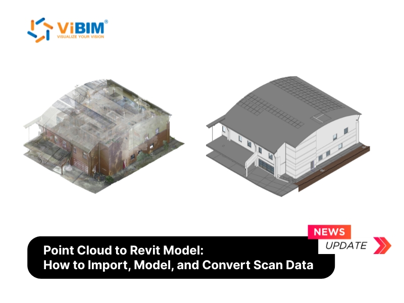
Point cloud to Revit modeling is the process of converting laser scan data into a parametric 3D Building Information Model (BIM) inside Autodesk Revit. The scan gives you millions of measured points from an existing building, and the conversion turns those points into intelligent elements such as walls, floors, and pipes that carry real data. The result is an as-built model a team can design and coordinate from, and because the tracing is manual, the order of work and the QC behind it decide how reliable it turns out.
Converting a point cloud to a Revit model follows a clear workflow, from importing the point cloud in a format Revit reads and setting up its display, to tracing the building discipline by discipline, to validating the finished model against the source cloud. How accurate and detailed it turns out depends on the LOD you set and how much you choose to model, more than on the hardware, though even a large Revit point cloud stays responsive only when you cap how many points are on screen at once.
Because no tool yet converts a scan into a deliverable model on its own, the real decision is whether those modeling hours stay in-house or go to a specialist. The sections below follow that path from import to delivery, the choices that drive quality, and where outsourcing fits inside the wider Point Cloud to BIM workflow.
What Is Point Cloud to Revit Modeling?
Point cloud to Revit modeling is the digital reconstruction of an existing building, where millions of scanned data points are traced into parametric Revit elements. A point cloud in Revit is a linked set of millions of laser-scanned points: purely geometric, showing where surfaces are without knowing whether a surface is a wall, a duct, or a column. The conversion adds that intelligence, producing parametric families that carry type, dimension, material, and phase data inside Revit software.
That distinction is what makes the output useful. Revit point cloud modeling turns the scan into a model that supports renovation and retrofit design on real existing conditions, as-built documentation, construction verification by overlaying the model on the scan, and a data foundation for facility management. It is one step inside the wider Point Cloud to BIM workflow, the reality capture path that runs from laser scanning to a finished model.
That scan data reaches you as files in specific formats, and Revit only reads some of them.
Point Cloud File Formats Revit Accepts
Revit reads point clouds in just two native formats, RCP and RCS. Every other format, including the open E57 standard, has to be indexed through Autodesk ReCap before Revit can link it. The format your scanning provider delivers decides whether you can link it straight away or need that one conversion step first.
The table below summarizes each format and when you will use it:
| Format | Source | Direct link in Revit? | When you will use it |
| RCP / RCS | Autodesk ReCap output | Yes. Best performance, spatially indexed | Default when you have ReCap, or the provider delivers native ReCap files |
| E57 | Open standard (ASTM E2807) | No. Index in ReCap Pro to RCP/RCS first | The common interchange format from most scanners; one ReCap step before linking |
| PTS, PTX, LAS, FLS, ZFS | Scanner-native / legacy | No. Convert via ReCap Pro to RCP/RCS | When the provider hands you raw scanner output |
In practice, an RCP project file points to several RCS scans, so you usually link the RCP and let it pull them together. A large E57 is best indexed to RCP/RCS in ReCap first, since ReCap spatially indexes the points for smoother display. Survey providers most often deliver native ReCap files, and our transfer spec is to keep each RCS under 5 GB or zip the dataset into one archive per transfer.
For a full breakdown of each one, see our guide to point cloud file formats.
How to Import a Point Cloud into Revit (Step by Step)
To import a point cloud into Revit, link the file through the Insert tab rather than importing it, then position it to match your project’s coordinate setup. Revit links point clouds as external references, so your project file stays small while the cloud data lives on disk.
The care this step gets carries through the whole project. The position, scale, and coordinate system set at link time become the reference every discipline traces against, and a cloud linked wrong shows up weeks later as misplaced geometry and remodeling hours.
Importing point cloud data into Revit takes four steps:
- Prepare and verify the scan data
- Link the file from the Insert tab
- Choose a positioning method
- Verify position and scale
Step 1: Prepare and Verify the Scan Data
Confirm the scan is registered, cleaned, and saved in a supported format before you link it.
- Registered: every scan position is stitched into one coordinate system. If you receive separate scans, run them through registration software such as ReCap Pro or Leica Cyclone first.
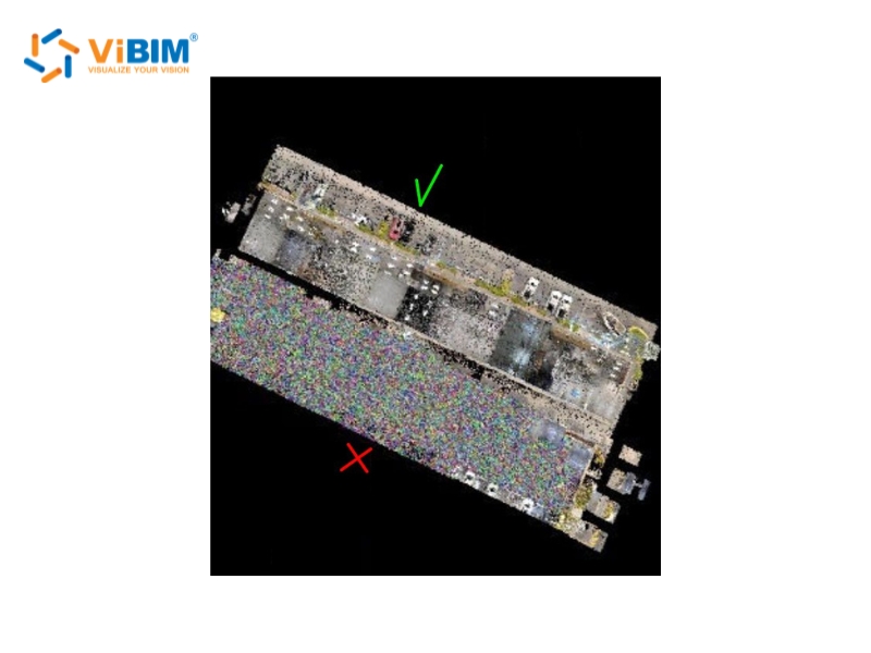
- Cleaned: noise is filtered out, meaning the people, vehicles, and temporary objects that moved during capture.
- Supported format: RCP or RCS. If you only have E57 or a raw scanner format, index it in ReCap Pro first.
An intake check at this stage catches three issues that derail modeling later: duplicate points, misaligned scan patches, and areas with no coverage. In ViBIM’s production workflow, these go back to the scanning provider for confirmation before any element gets modeled.
Step 2: Link the Point Cloud from the Insert Tab
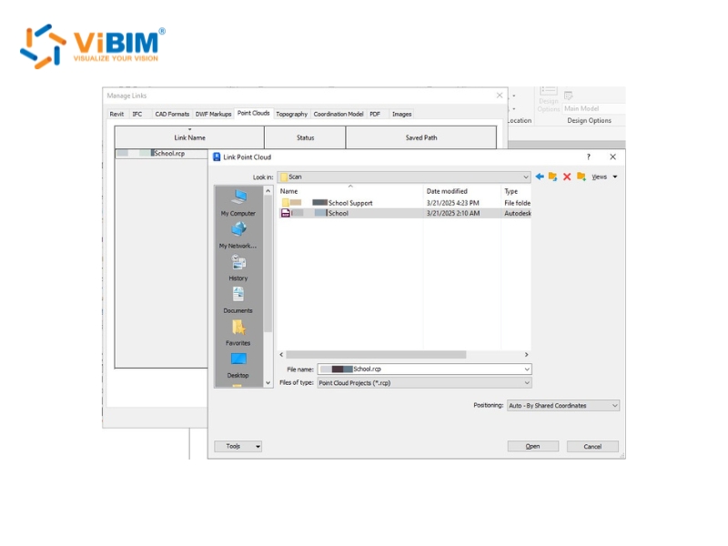
Go to the Insert tab in your Revit project, and in the Link panel choose Point Cloud.
- Open the Insert tab. In the Link panel, click Point Cloud.
- Browse to your RCP or RCS file and select it.
- Set the Positioning method (Step 3 covers which to pick).
- Click Open. Revit retrieves the current version of the file and links it into the project.
Revit links point clouds, it does not embed them, so the RVT file stays small no matter how large the scan is.
Worksharing tip: in a Central/Local setup, linking a massive cloud over the network slows everyone down. Keep a copy of the cloud file on each user’s local drive at the same path, for example C:\PointClouds. Revit uses relative paths, so every machine reads its own local copy even when the usernames differ.
If the cloud loads but you cannot select it afterward, the cause is usually a visibility setting, a workset, or a lock, and each needs a different fix: see Revit cannot select the point cloud.
Step 3: Choose the Positioning Method
For most building projects, Auto – Origin to Origin is the safest default. It places the cloud’s origin at Revit’s internal origin and keeps coordinates predictable.
- Auto – Origin to Origin: the default for scans that use a local coordinate system. Watch for scans that carry large surveyor coordinates, which can push the cloud far from your workspace.
- Auto – Center to Center: for a quick look only. It aligns bounding-box centers and has no coordinate accuracy, so you will reposition later.
- Auto – By Shared Coordinates: for georeferenced data that has survey control points.
- Auto – Origin to Last Placed: appears from the second scan onward, and stacks multiple files from the same site consistently.
On client projects, the positioning method is usually set during project setup. ViBIM links per the client’s coordinate spec, typically Origin to Origin or Shared Coordinates.
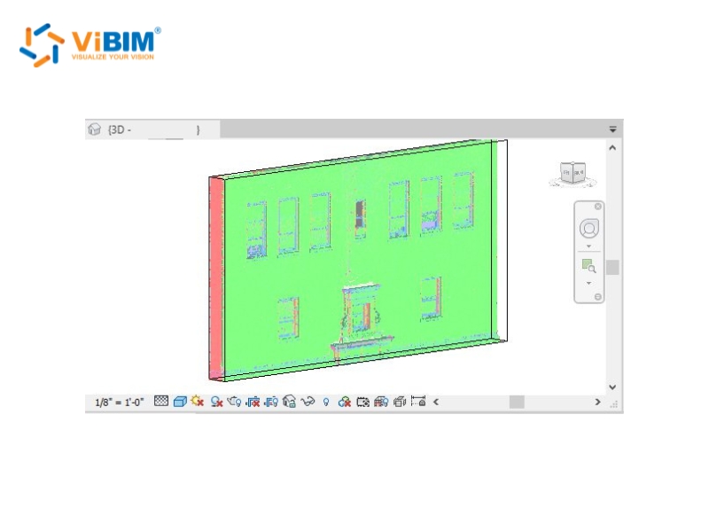
Step 4: Verify Position and Scale
Open a 3D view right after linking and confirm the cloud loaded where you expect it.
- Check that the cloud sits in the right place relative to your project geometry and origin.
- Check scale by measuring one known dimension you can read in the scan, such as a window opening or a column spacing, with the Measure tool.
- If it needs adjusting, use Move or Rotate, or remap it in Manage Links.
A two-minute check here saves hours of rework, because everything you model next inherits the cloud’s position and scale.
To see how to import a point cloud into Revit in real time before any modeling begins, this Revit point cloud walkthrough covers it from linking the file through the display and view-range settings.
A linked cloud still has to be readable before you can model from it, which comes down to how you display, isolate, and measure it.
Using Point Clouds in Revit: Display, Isolation, and Measurement
Using a point cloud in Revit comes down to three controls: display settings, view isolation, and measurement snapping. Master these three and point cloud modeling in Revit stays manageable even on a billion-point scan, without touching the source file or your performance settings.
Display settings
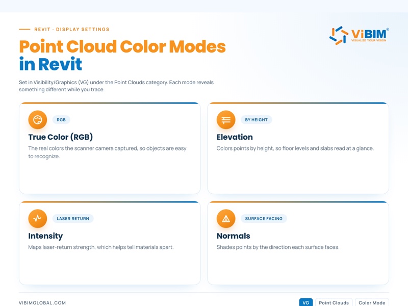
Control how the Revit point cloud renders through the Visibility/Graphics dialog (shortcut VG), under the Point Clouds category. The color mode you choose changes what reads at a glance:
- True Color (RGB): the real colors the scanner’s camera captured, which makes objects easy to recognize.
- Elevation: colors points by height, so floor levels read at a glance.
- Intensity: maps laser-return strength, which helps tell materials apart.
- Normals: shades points by the direction each surface faces.
You can also set point size per view to keep the cloud from hiding the geometry you are tracing.
Section boxes
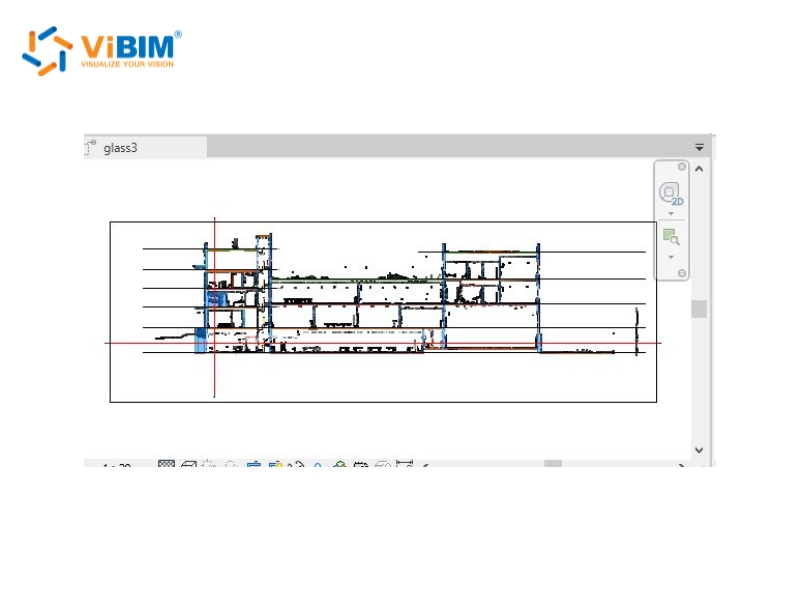
A section box crops the visible cloud to just the room, floor, or bay you are modeling. In a 3D view, turn on the Section Box and drag its faces to isolate the area. In plan and section views, the crop region and View Range do the same job, and cutting the plan at about 4 ft (1.2 m) brings window and door openings into clear view.
ViBIM modelers set up a standard view kit per area before modeling: two vertical sections, one plan section, and a 3D view, with cuts placed at windows and just under ceilings where MEP runs concentrate. Complex intersections get temporary section views as needed.
Measuring and snapping
Revit snaps directly to points in a linked cloud, so you can measure and place geometry against the scan. Use the Measure tool (DI) to snap between points, create levels and reference planes by snapping to floor and ceiling surfaces, and set wall or floor positions straight from the cloud as you trace. Snapping is most reliable when you zoom in close at a workable point density. Zoom out, where points thin and overlap, and a snap can land slightly off.
Turning those points into walls, beams, and ducts is where the real modeling work begins.
How Do You Create a Revit Model from a Point Cloud?
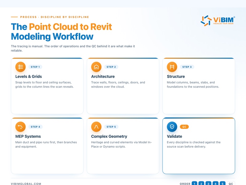
To create a Revit model from a point cloud, work in a fixed order: set up levels and grids from the scan, then trace architecture, structure, and MEP over the cloud, discipline by discipline. The tracing itself is manual. What makes it fast and reliable is the order of operations and the QC behind it.
The workflow runs in five parts:
- Set up levels and grids from the scan
- Model architectural elements
- Model structural framing and foundations
- Model MEP systems
- Handle complex and heritage geometry
1. Set Up Levels, Grids, and Work Planes First
Create levels by snapping to floor and ceiling surfaces in the cloud, then place grids on the column lines the scan reveals.
Measure floor-to-floor heights straight from the cloud by snapping between two slab surfaces, set grids to the real column positions, and add work planes for sloped or irregular areas. Project setup decides how smoothly the rest of point cloud modeling in Revit goes.
ViBIM teams start every job from a Central file: the client’s Revit template when one is provided, otherwise a default template checked for the right version, units, and coordinates, with each modeler working in a Local copy.
2. Model Architectural Elements from the Scan
Trace walls, floors, and ceilings in plan and section views, using the scan as the dimensional reference.
- Walls and curtain systems: trace them in plan and section views over the cloud.
- Floors, roofs, and ceilings: set each at the correct elevation read from the scan.
- Doors and windows: place each family at the width and head height read from the cloud slices, so a window matches its scanned opening.
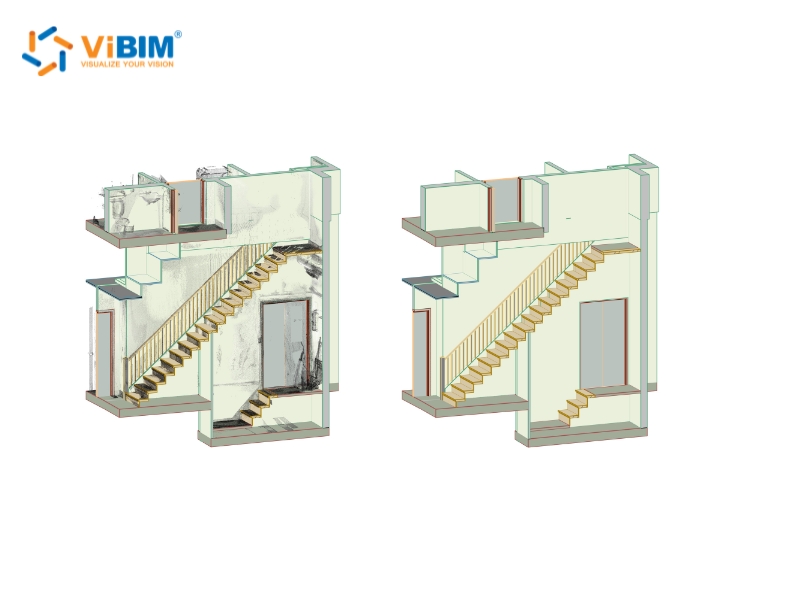
- Stairs and railings: add these once the primary shell is in place.
Prefer Revit System Families for walls, floors, and roofs, because they are lightweight and data rich. Save unusual geometry for the dedicated method covered further down.
3. Model Structural Framing and Foundations
Build the structural frame to match the scanned positions, modeling columns, beams, slabs, and foundations.
Cover the load-bearing elements such as beams, columns, floor slabs, foundations, and load-bearing walls, and separate the structural system from the architecture wherever the cloud lets you read it. Model rebar only when the project scope calls for it. Validate critical dimensions against several cross-sections of the cloud rather than trusting a single slice, which sets up the formal checks later.
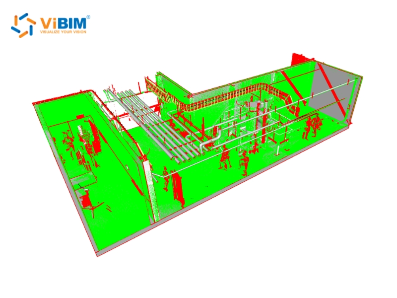
4. Model MEP Systems
Model MEP in two passes:
- Main runs first. Duct, pipe, cable tray, and conduit runs go in first, starting where systems concentrate: just under ceilings, along corridors, in risers, and in plant rooms.
- Branches and equipment second. Branch lines through offices, stairwells, and lobbies come after, so every run closes out complete. Standalone equipment such as pumps, AHUs, chillers, valves, fire-protection devices, lighting, sensors, and sockets is built as separate families. When a manufacturer part has no ready Revit family, that becomes dedicated Revit Family Creation services work, with each family cleaned up and given materials before it loads into the project.
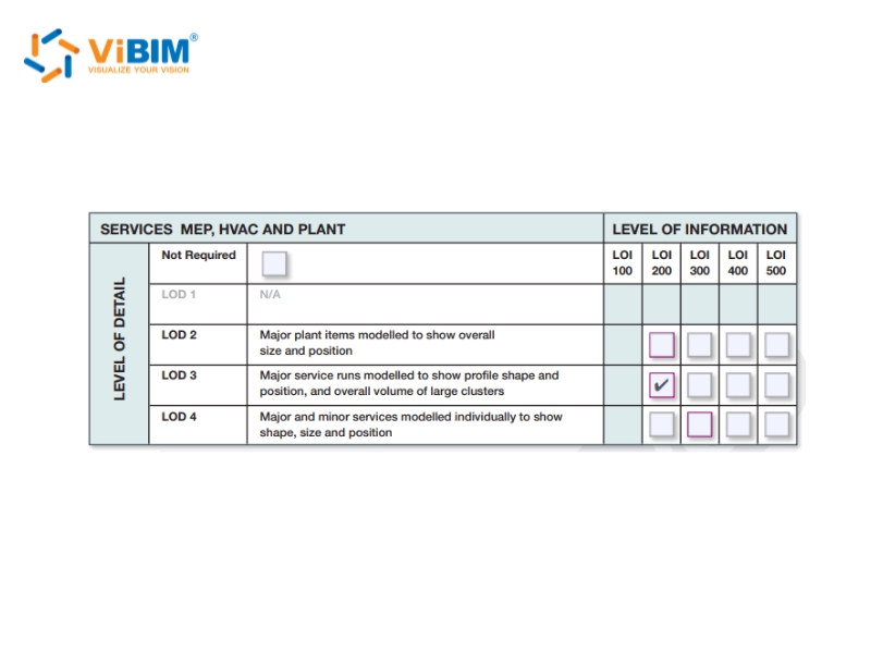
Coordination-critical MEP is usually modeled to LOD 350, the level of development that carries enough geometry and data for clash coordination.
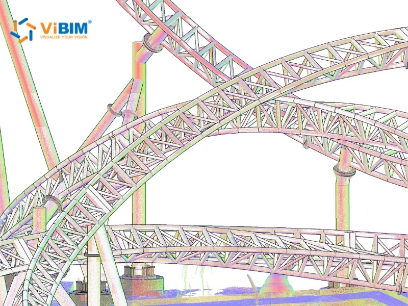
5. Handle Complex and Heritage Geometry
Choose the modeling method by how far the real geometry deviates from plumb and level.
- Small deviations, near plumb and level: standard parametric families, which stay fast and data rich.
- Significant deviations, leaning or curved walls: Revit’s Model In-Place or massing, to hold the as-is accuracy. Overusing in-place families makes the file heavier and harder to manage, so reserve them for the elements that truly need them.
- Deformation you have to document exactly: keep it as mesh or handle it outside Revit, instead of forcing it into a family.
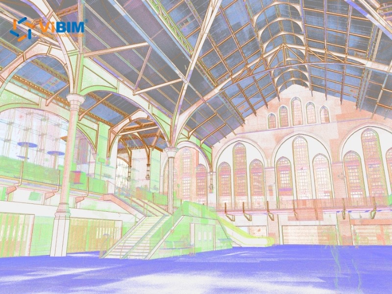
For complex, repeating geometry, Dynamo scripts generate elements from point lists, which ViBIM uses in production. This comes up most on heritage work such as historical churches and museums, where almost nothing is truly straight.
A model that looks finished is not always a model that matches the scan.
Validate the Model Against the Source Scan
Validating a point cloud to Revit model means overlaying the finished elements on the source scan and checking for deviation, missing objects, and file health before delivery. Checks run in two environments: section-based checks inside Revit, then deviation and completeness checks in Navisworks.
Tolerance always follows the project spec and the quality of the scan, so the goal is a Revit model from point cloud data that matches the as-built conditions to that agreed standard, not a fixed millimeter figure.
Dimensional and Section Checks in Revit
Cut paired sections through the model and the cloud, and measure where they disagree.
ViBIM’s section protocol runs one horizontal cut per level, prioritized at window lines and just under ceilings, plus vertical cuts along the building’s two main axes through elevator shafts, risers, and plant rooms.
A cut through that same window opening, for instance, shows at once whether the modeled family drifted from the scanned reveal. Use Measure Between References for the critical dimensions, and when a deviation runs past the spec, correct the element, never the cloud.
Deviation and Clash Checks in Navisworks
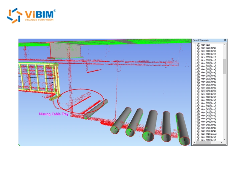
Link the Revit model and the cloud into Navisworks to catch what section views miss.
Navisworks surfaces the small objects that are hard to see in Revit, such as valves, minor equipment, and lighting, along with Navisworks clash detection between disciplines and how well the model parts agree with each other. A pre-analysis tool (3DR) flags common missing, alignment, and tolerance issues automatically, and the filtered result goes into Navisworks review with color-coded objects and zoned checking so no area gets skipped.
A final file-health pass closes the project out:
- Consistent naming for views, families, types, materials, and files
- Correct levels, worksets, and phases
- Resolved warnings
- Purged unused content
Together, the Revit section pass and the Navisworks pass form the two independent QC layers every ViBIM project clears before delivery.
All of this checking happens with the model and a billion-point scan open at once, which is exactly when Revit slows down.
Manage Performance with Large Point Cloud Datasets
To keep Revit responsive with a large scan dataset, limit how many points it has to draw at once. The slowdown comes from display load, not file size, because the cloud is a linked reference rather than embedded geometry. Building-scale scans commonly run to hundreds of gigabytes, so the job is to keep Revit drawing only what you need.
Seven tactics cover most performance problems:
- Use section boxes aggressively to isolate the area you are modeling.
- Lower the displayed point density per view when the cloud crowds the geometry.
- Model in plan and section views, which render lighter than a 3D perspective, and use 3D mainly to verify.
- Close views you are not using, since each open view adds to the render load.
- Put the Revit point cloud on its own workset, so the whole team can toggle its visibility in one click.
- Decimate the cloud through ReCap for an extremely large dataset. In ViBIM’s production workflow, a controlled decimation keeps roughly 5 to 10 percent of the core points, which still holds every surface you trace while cutting the file weight dramatically.
- Split a multi-building or multi-floor dataset into separate files per level or zone, another ViBIM practice, so each modeler loads only the area being traced and the full site only comes together for coordination checks.
For very large datasets, or several teams working at once, stream the cloud through Cintoo Cloud or Autodesk Construction Cloud instead of copying it all to every machine. Back that with a high-performance workstation and enough RAM for the dataset.
Those tools manage the weight of the data, but they do not remove the modeling work itself.
Can You Convert a Point Cloud to Revit Automatically?
No, no production-ready tool converts a point cloud into a deliverable Revit model automatically. Automation tools output mesh geometry, while a deliverable BIM model needs parametric Revit families that carry type, material, and phase data. AI-assisted tools can speed up parts of the work, but element classification and family assignment stay manual.
A converter does not decide on its own that one surface is a wall, another a duct, and another a column. To convert a point cloud to a Revit model that a contractor can build from, you need that semantic classification, the right family and type for each element, and the relationships between them, which is construction knowledge rather than geometry alone.
ViBIM runs automation where it actually works: internal Revit API tools and Dynamo scripts for repetitive geometry, plus an in-house AI toolset, Aina-Aimo, under development to speed up the first-pass model. Even with those, every element still passes two independent QC layers against the source cloud.
The table below shows what each tool category actually delivers next to manual modeling:
| Tool category | Output | Gap vs deliverable BIM |
| Mesh converters (Pointfuse, Cintoo) | Mesh or NWC | No parameters, no families |
| Semi-automatic / AI-assisted (EdgeWise pipes, BricsCAD Point Cloud Classifier and Detect Rooms) | Partial geometry detection | Manual verification and reclassification |
| Manual tracing over a linked cloud | Parametric Revit families | The production standard today |
Treat AI as an assistant, not a converter. It clears some of the repetitive geometry work, but a person still decides what each element is and confirms it against the scan. That is why a deliverable Scan to BIM Service still depends on skilled modelers and a real QC pass.
With full automation off the table, the real choice is whether you handle the point cloud to Revit modeling in-house or hand those modeling hours to a specialist.
Point Cloud to Revit Modeling: DIY or Outsource?
Model in-house when you have Revit capacity and recurring scan-to-model work. Outsource when deadlines, LOD requirements, or dataset size outgrow your team.
Four factors decide who should build the 3D Revit model from point cloud data:
| Factor | Model in-house when… | Outsource when… |
| Team skills | You have Revit modelers who understand construction | You lack people who can read a cloud into building elements |
| Volume and LOD | The work is occasional, around LOD 200 | You need LOD 300+ regularly, with MEP coordination |
| Deadline | The schedule is flexible | The date is fixed, such as a renovation or bid deadline |
| QC infrastructure | You have your own checking process | You need independent, multi-layer QC |
As a point of reference on the outsourced side, a point cloud to Revit conversion of 10 to 100 hours typically ships in 1 to 4 business days, new projects get a quote within 12 to 24 hours, and a free trial lets a new client calibrate quality before committing.
ViBIM has delivered this across 1,000+ Scan-to-BIM projects and 250,000+ modeling hours since 2014, at a 99% on-time rate. Established 3D BIM Modeling service providers bring that scale of capacity and the independent QC an in-house team rarely keeps spare.
For the wider path from raw scan to deliverable model, see our Point Cloud to BIM guide.

How Do You Convert a Point Cloud to a Revit Model?
To convert a point cloud to a Revit model, link the registered scan into Revit, then trace levels, grids, and each discipline over the cloud before validating the finished model against the scan. No tool converts a scan into a deliverable model on its own, so the modeling stays manual and the QC decides how reliable the point cloud to Revit conversion turns out.
How Long Does It Take to Create a Revit Model From a Point Cloud?
It depends on the LOD, the building’s complexity, and the scan quality. A small architectural shell can take a few days, while a coordination-grade MEP model runs to a few weeks. As a real benchmark, a 10 to 100 hour scope typically ships in 1 to 4 business days.
How Accurate Is a Point Cloud to Revit Model?
Accuracy depends on the scan quality, the registration, and the tolerance spec the project sets. The model is verified directly against the source cloud to that spec, so it matches the as-built conditions to the agreed standard rather than a single fixed number.
Is a Revit Model From a Point Cloud the Same as an As-Built Model?
Yes, as a product. A model that reflects the building’s condition at the time of the scan is an as-built model. Point cloud to Revit modeling is the process that produces it.
What Is a Point Cloud in Revit?
A point cloud in Revit is a linked reference of millions of laser-scanned points that you trace over, not geometry you edit or that lives inside the file. The points record measured surfaces but carry no building intelligence, so you model parametric walls, floors, and pipes on top of them and keep the cloud as the dimensional backdrop of the point cloud to Revit workflow.
What Point Cloud Files Does Revit Import?
Revit links two native formats, RCP and RCS; every other format, including E57, has to be indexed in Autodesk ReCap first. Ask your scanning provider for RCP or RCS where possible, so the point cloud to Revit conversion starts without the extra ReCap step.
Can You Use Point Clouds in Revit LT?
No. Revit LT does not support point clouds; linking a point cloud needs full Revit. If you only have Revit LT, index and inspect the scan in ReCap, but the modeling has to move to a full Revit license.
How Do You View and Adjust a Point Cloud in Revit?
You control a linked point cloud through display settings, view isolation, and measurement snapping, not by editing the points themselves. Set the color mode and displayed density in Visibility/Graphics, crop the view with a section box, and snap the Measure tool to points to read real dimensions.
How Do You Change the Way a Point Cloud Displays in Revit?
Open Visibility/Graphics, and under Point Clouds set the color mode and lower the displayed point density when the cloud crowds your geometry. Revit has no single point-size slider, so you manage clarity with density, color mode, and section boxes.
How Do You Move, Rotate, or Scale a Point Cloud in Revit?
Use Move or Rotate to reposition the linked cloud, or remap it in Manage Links; you do not scale it. A registered scan already carries real-world scale, so if a dimension reads wrong the cause is units or registration, which you confirm with the Measure tool.
How Do You Delete or Unload a Point Cloud in Revit?
Select the linked cloud and delete it, or unload it in Manage Links to keep the reference without drawing it. Unloading is the usual choice, since it frees display load while leaving the link in place.
Why Can’t You See a Point Cloud in Revit?
A cloud that links but does not show is almost always a visibility setting: the Point Clouds category is off in Visibility/Graphics, the view range or section box crops it out, or its workset is closed. Check those first, then confirm the link path resolved in Manage Links. If the cloud shows but will not select instead, that is a separate fix covered in the guide linked above.