A Scan-to-BIM checklist is a structured list of tasks and requirements that covers the entire process — from 3D scanning and point cloud processing to creating and validating the final Building Information Model (BIM). A checklist serves as a detailed roadmap, guiding every phase of the project from initial planning to final handover. It ensures that no critical step is missed, standards are consistently met, and all stakeholders are aligned.

What is a Scan to BIM Checklist and Why is it Crucial for Your Project?
A Scan to BIM checklist is a structured document that outlines every task, standard, and deliverable required throughout the Scan to BIM workflow. It acts as a quality control and project management tool to help project teams streamline workflows, maintain consistency, and deliver high-quality results.
A detailed Scan to BIM checklist provides four key benefits:
- Ensuring Process Consistency: It standardizes the workflow across projects and teams, ensuring accuracy and maintaining a consistent level of quality and detail in the resulting BIM model.
- Minimizing Errors and Rework: By outlining each step, from data capture to modeling, the checklist helps teams navigate common Scan to BIM challenges early, drastically reducing the risk of costly errors and rework down the line.
- Improving Communication and Collaboration: A shared checklist ensures that all team members—from surveyors to BIM modelers—understand their roles, responsibilities, and the project’s requirements, fostering seamless collaboration.
- Setting Clear Expectations: It provides project stakeholders, including clients and facility managers, with a transparent view of the process, deliverables, and quality standards, ensuring everyone is on the same page.
- Aligning Scope with Clients: The checklist serves as a tool to confirm project scope, agreed deliverables, and acceptance criteria with clients. This helps avoid misunderstandings, supports smoother approvals, and ensures that final handovers fully match client requirements.
Based on ViBIM’s practical experience, the use of a Scan-to-BIM checklist largely depends on the client profile.
For new clients, where workflows and expectations regarding deliverables and quality standards are not yet fully aligned, the checklist serves as an effective tool to clarify requirements and establish a shared understanding from the outset.
For long-term or recurring clients, the checklist is rarely used. Instead, communication is streamlined through key requirements exchanged via email. At this stage, ViBIM’s technical expertise and domain knowledge are critical in interpreting broad client objectives, analyzing project needs, and defining a precise scope of work. With today’s accelerated project timelines, requiring clients to complete a comprehensive checklist at project kickoff is often impractical. ViBIM bridges this gap by leveraging its experience to optimize time, ensure accuracy, and maintain consistent quality in deliverables.
To understand how each checklist item fits into the complete production process—from initial site capture through final model delivery—explore our comprehensive breakdown of the Scan to BIM workflow to see how each phase connects and builds upon the previous stage for successful project execution.

The Scan to BIM Process: A 7-Phase Checklist
The Scan to BIM process can be broken down into seven distinct phases. Following this checklist ensures a comprehensive and accurate transition from a physical site to a digital model.
Phase 1: Pre-Scan Planning and Project Scoping
The Pre-Scan Planning and Project Scoping phase involves five critical steps that establish a clear project foundation, preventing the scope creep and budget overruns common in AEC projects. This initial phase is essential to ensure the final BIM model is fit for its intended purpose and meets all stakeholder expectations:
- Define the Scope of Work (SOW): Clearly document the project goals, the specific areas to be scanned, and the elements to be modeled.
- Determine the Level of Detail (LOD): Agree on the required LOD for the model. The LOD specification dictates how much detail and data will be included in each model element.
- Identify Intended Use: Specify the purpose of the final BIM model, such as for renovation design, as-built verification, clash detection, or facility management.
- Agree on Deliverables: Finalize the required file formats for the final handover (e.g., Revit (RVT), Industry Foundation Classes (IFC), DWG).
- Establish a Quality Control (QC) Process: Define the procedures for quality checks at each phase of the project.
To make informed decisions during project scoping and accurately define modeling requirements that align with your budget and timeline, learn the key distinctions in our detailed comparison of the difference between LOD 300 and 350 to choose the appropriate level of detail for your specific use case.
Phase 2: Site Preparation and Safety
The Site Preparation and Safety phase involves three essential steps that ensure the physical environment is ready for scanning, guaranteeing both data accuracy and the safety of the survey team.
Select the Right 3D Laser Scanning Equipment:
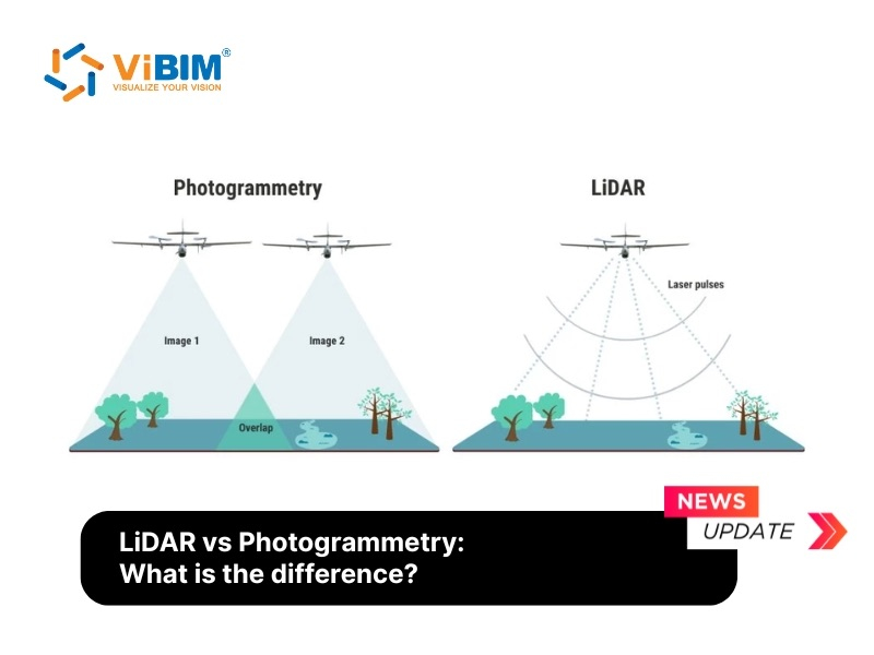
- Terrestrial laser scanners → for high-accuracy documentation
- Handheld/mobile scanners → for quick scans in tight or complex spaces
- Drone-based LiDAR → for large-scale outdoor or inaccessible projects
Plan Scanning Locations & Coverage Areas:
- Consider lighting, obstructions, and accessibility
- Perform reconnaissance to determine optimal scanner placement
Schedule Scanning During Low Activity: Conduct scanning during downtime or low-traffic hours to minimize disruptions and data anomalies.
Ensure Site Access & Safety Compliance:
- Obtain necessary permits and approvals
- Follow all health and safety regulations
Phase 3: Data Capture (3D Laser Scanning)
This is the on-site phase where the physical environment is captured using 3D laser scanners. The accuracy of this phase directly impacts the quality of the final BIM model:
Selecting scanning equipment: It is essential to select the appropriate scanning equipment based on the project’s scale, complexity, and accuracy requirements. Different types of scanners offer distinct advantages and limitations:
| Scanner Type | Best For | Pros | Cons |
| Terrestrial Laser Scanners | High-accuracy documentation of buildings, industrial plants, and infrastructure. | Extremely high accuracy and detail. | Slower capture time; requires multiple setups. |
| Mobile Laser Scanners | Large-scale projects or areas with complex geometries where speed is critical. | Rapid data capture; covers large areas quickly. | Lower accuracy compared to terrestrial scanners. |
Point Cloud Scanning: A point represents the position of a surface relative to a 3D laser scanner. A point cloud is formed by combining millions of these points into a single, highly precise digital dataset. Using advanced laser scanning systems such as Faro, Trimble, Riegl, and Leica, multiple scans are captured and merged to generate an accurate digital representation of a building. This process delivers a comprehensive view of the structure, ensuring the final model reflects true site conditions.
Phase 4: Point Cloud Processing and Registration
Once the on-site scanning is complete, the raw data is transferred to the office for processing. In this phase, the individual scans are cleaned, aligned, and stitched together to create a single, cohesive point cloud:
Register & Align Point Cloud Data
- Align and stitch multiple scans into a single, unified dataset. This critical step of point cloud registration ensures all spatial data is geometrically correct.
- Define the final file format (.rcp, .e57, .pts, .las)
- Use the best Scan to BIM software like Autodesk ReCap, Faro Scene, or Leica Cyclone to manage these large datasets efficiently.
Remove Noise & Unwanted Artifacts
- Filter out moving objects, reflections, and redundant points
- Clean data to eliminate people, vehicles, or other transient objects captured during scanning
Convert Point Cloud to a Unified Model
- Export into interoperable formats (.e57, .rcp, .las) for use in BIM software
- Optimize file size for faster processing and smoother project workflows
Quality Assurance & Accuracy Checks
- Verify alignment against site control points, survey benchmarks, and project documentation
- Compare with original floor plans or site drawings to confirm accuracy
- Ensure scaling and orientation are consistent with project requirements
Phase 5: BIM Modeling
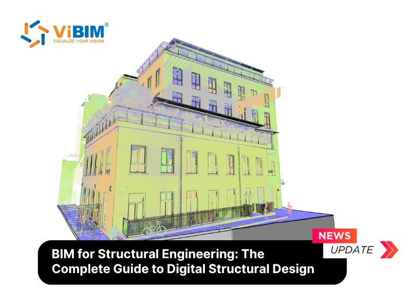
In 3D BIM modeling, real-world point cloud data is transformed into a digital representation of the project. The point cloud scan is first verified and inserted into BIM software, after which modelers create an as-built 3D BIM model. This model can then be used for renovation, refurbishment, retrofit, and reconstruction purposes.
Here’s the step-by-step checklist for BIM modeling:
Importing Point Cloud into BIM Software
- Load the registered point cloud into platforms like Autodesk Revit, ArchiCAD, or Bentley MicroStation
- Adjust the coordinate system to guarantee proper alignment
- Adhere strictly to the established naming conventions for files, worksets, and model families.
Creating Architectural, Structural, and MEP Elements
- Extract core building components including walls, doors, windows, columns, beams, ducts, and pipes
- Define the appropriate Level of Detail (LOD) based on project scope and requirements
Defining Metadata & Asset Tagging
- Assign material properties, dimensions, and classification details to modeled elements
- Apply COBie standards to support facility management integration
To delve deeper into our in-house standards and workflows, you can access ViBIM’s Scan to BIM checklist here. This internal document provides a comprehensive breakdown of tasks, naming conventions, quality checkpoints, and modeling protocols we consistently apply to ensure accuracy, compliance, and efficiency across all BIM projects.

Phase 6: Quality Assurance and Control
Continuous Scan to BIM quality control is vital to ensure the final BIM model is an accurate and reliable digital twin of the physical asset. This phase involves a series of rigorous checks to validate the model against the source data and project requirements:
Perform Model Validation & Error Checking
- Compare the BIM model systematically against the registered point cloud to detect deviations in geometry or positioning
- Conduct BIM audits to verify model accuracy and completeness
- Ensure that the specified Level of Detail (LOD) requirements from the planning stage are consistently met
- Engage project stakeholders in reviewing and confirming the model’s accuracy
Run Clash Detection Across Disciplines
- Use tools such as Navisworks to identify conflicts or intersections between architectural, structural, and MEP elements
- Resolve clashes proactively before construction begins to reduce costly rework and scheduling delays
Refine Model for Final Approval
- Make necessary adjustments based on QA/QC feedback and stakeholder comments
- Audit and purge the model to remove unused elements, redundant families, and unnecessary views, optimizing performance and file size
- Finalize the BIM model for handover to clients or project teams, ensuring compliance with project scope and deliverable standards
Phase 7: Deliverables and Handover
The final phase involves compiling all project deliverables and formally handing them over to the client. A smooth handover ensures the client can immediately begin using the BIM model for their intended purpose:
Exporting BIM Models
- Deliver models in multiple formats such as .RVT (Revit) for full BIM modeling, .IFC for interoperability across platforms, .DWG for 2D drawings, and .NWC/.NWD (Navisworks) for clash detection and coordination.
- Provide additional documentation files such as PDFs when required.
Generating Sheets, Schedules & Reports
- Produce floor plans, sections, and elevations extracted from the BIM model.
- Export BIM schedules for materials, quantities, and asset information, ensuring they are aligned with project requirements.
- Submit a comprehensive final report covering scanning parameters, registration accuracy, and key findings.
Model Sharing via Collaboration Tools
- Upload the finalized BIM model into collaboration platforms such as BIM 360, Procore, or Trimble Connect for real-time access.
- Conduct virtual handover meetings and model reviews with clients and contractors to present the model structure, explain key elements, and clarify any project-specific requirements.

Scan to BIM Checklist for Specific Disciplines
While the 7-phase process provides a general framework, different disciplines require a focus on specific elements.
Architectural Scan to BIM Checklist
The architectural checklist focuses on accurately capturing the building’s form, finishes, and spatial layout to ensure the model is a true digital twin of the physical space.
- Focus on: Walls, doors, windows, floors, ceilings, roofs, stairs, and other major architectural features.
- Verify: Room dimensions, ceiling heights, and locations of openings are accurate.
- Include: Key fixtures like cabinetry, millwork, and permanent furniture if required by the SOW.
For example, it’s critical to specify in the SOW if non-permanent fixtures like office cubicles should be excluded to manage modeling scope and cost. Factors like complexity and scope heavily influence the final 3D laser Scan to BIM services price.
Learn more about our Architectural Scan to BIM Services.

MEP (Mechanical, Electrical, Plumbing) Scan to BIM Checklist
The MEP checklist prioritizes modeling all major systems and components, with a key focus on ensuring accurate clearances and system connectivity for clash detection and coordination.
- Focus on: Main ductwork, piping runs, cable trays, conduits, major vents, light fixtures, and significant mechanical equipment (boilers, chillers, AHUs).
- Specify: The minimum size of components to be modeled. It’s common practice to exclude elements smaller than a certain diameter (e.g., 2 inches or 50mm) unless specified otherwise.
- Verify: Clearances and access zones around major equipment are accurately represented.
Explore our specialized MEP Scan to BIM Services.

Structural Scan to BIM Checklist
The structural checklist is designed to capture all load-bearing elements and their critical connections, providing the foundational data needed for structural analysis and verification.
- Focus on: Primary structural elements such as beams, columns, trusses, bracing, and foundations.
- Verify: The size, location, and orientation of all structural members.
- Include: Major structural connections and slab thicknesses as defined by the project’s LOD requirements.
For example, the checklist must define if major structural connections for steel frames are required, as this data is critical for structural analysis software and is often tied to higher LOD requirements.
Discover our detailed Structural Scan to BIM Services.

A meticulous Scan to BIM checklist is the key to transforming a complex process into a manageable and predictable workflow. By adopting this structured approach, you can ensure your project benefits from the highest levels of accuracy, efficiency, and collaboration.
Ready to ensure the success of your next renovation or as-built project? Contact ViBIM today to learn how our expert Point Cloud to 3D Model services can provide you with the accurate, reliable, and intelligent models you need.
ViBIM – Revit Modeling Outsourcing
- Address: 10th floor, CIT Building, No 6, Alley 15, Duy Tan street, Cau Giay ward, Hanoi, Vietnam
- Phone: +84 944 798 298
- Email: info@vibim.com.vn