The Scan to BIM process involves using 3D laser scanners to capture the as-built conditions of a physical space and converting that data into a Building Information Model (BIM). This technology is revolutionizing renovation, retrofit, and facility management projects by providing a highly accurate digital representation of existing structures. For architects, engineers, and construction professionals, mastering this process means getting familiar with its unique language. Understanding the specific terminology is crucial for successful project execution, clear communication among stakeholders, and ensuring the final model meets project requirements.
This glossary provides definitive explanations for 17 key Scan to BIM terms, organized by their function in the Scan to BIM workflow, to help you navigate your next project with confidence.

Reality Capture
Reality capture is a technology-driven approach used to generate precise digital representations of physical environments, typically through 3D laser scanning or photogrammetry. By collecting spatial data such as geometry, textures, and colors with advanced sensors like LiDAR or high-resolution cameras, the captured information is processed into point clouds or 3D models that serve as accurate as-built documentation of existing conditions. This allows millimeter-level accuracy in replicating dimensions, geometries, and object positions, ensuring reliable project documentation.
Through reality capture, BIM (Building Information Modeling) acquires precise site data that plays a vital role in design, construction, and facility management. Project accuracy is enhanced through reduced errors and rework, improved coordination, and support for virtual walkthroughs and analysis. It also strengthens asset management by providing detailed digital records for maintenance, renovation, or historical preservation. Ultimately, reality capture within BIM enables the creation of a 3D digital twin, forming the foundation for long-term lifecycle management.

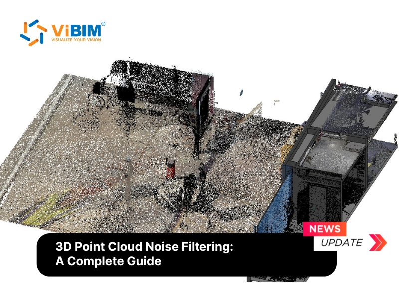
Point Cloud
A point cloud is a collection of data points plotted in a three-dimensional coordinate system, capturing the external surfaces or interior spaces of an object or environment. Each point in a point cloud represents a specific location in 3D space and may include additional attributes such as color or intensity, captured through technologies like laser scanning or photogrammetry. These points are generated through laser scanning, where laser beams are used to measure distances and capture the physical shape and dimensions of objects or environments, often stored in standard point cloud file formats.
The use of point cloud modeling extends beyond the AEC industry (architecture, engineering, and construction) to fields such as virtual reality, video game development, and environmental modeling, where point cloud segmentation is frequently used to isolate specific features within the datasets.

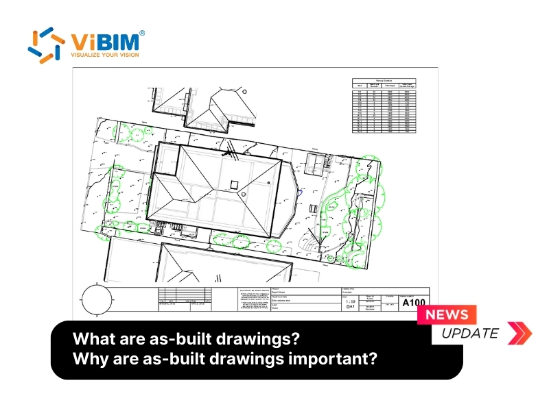
As-Built Model
An As-Built Model is a BIM that accurately reflects the existing conditions of a building as it was actually constructed, including any modifications or deviations from the original design plans. It captures the actual conditions of the building, documenting exact dimensions, locations of structural, mechanical, hydraulic, electrical, and architectural elements, along with additional data such as technical specifications, manuals, and photographic documentation.
In a professional 3D Scan to BIM workflow, the point cloud data is used to create this model. Unlike a design model for a new building, an as-built model is a digital record of reality, providing precise information on the location, size, and orientation of structural and MEP (Mechanical, Electrical, and Plumbing) elements.

3D Laser Scanning
3D Laser Scanning is a technology that captures precise three-dimensional information of physical objects or environments using laser light. It works by projecting laser beams onto a surface and measuring the time it takes for the laser pulses to reflect back to the scanner’s sensor (LiDAR). This time measurement helps calculate the exact distance between the scanner and the object’s surface. Multiple scans are typically required from different positions to capture a complete space without any gaps or shadows. The scanner gathers millions of data points, creating a dense “point cloud” that represents the shape and dimensions of the scanned object in 3D space.
This point cloud data can then be processed and converted into highly detailed 3D digital models, maps, or representations for various uses, including engineering, construction, architecture, quality control, reverse engineering, heritage preservation, and forensics. Modern 3D laser scanners are portable, safe, fast, and accurate down to millimeters.

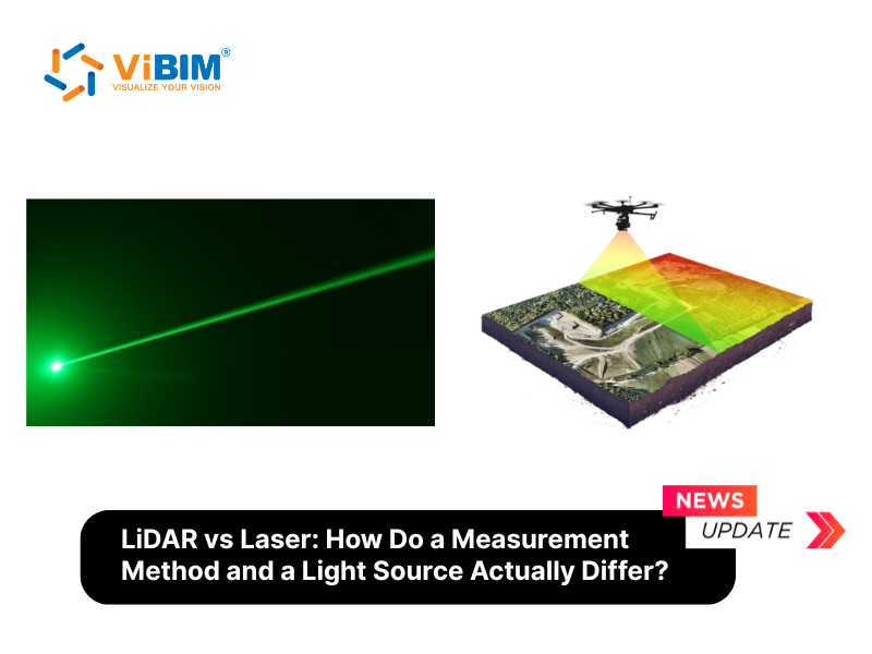
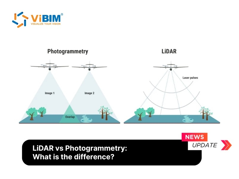
LiDAR (Light Detection and Ranging)
LiDAR (Light Detection and Ranging) is a remote sensing technology that measures distances by emitting laser pulses and calculating the time it takes for the light to return after reflecting off objects. While often used interchangeably with 3D laser scanning, LiDAR is the core technology within most terrestrial laser scanners. It calculates distance by measuring the time it takes for the laser pulse to travel to a surface and reflect back to the sensor. This technology is known for its high accuracy and ability to capture vast areas quickly.
This method is widely applied in topographic mapping, forestry, autonomous vehicles, and construction to capture highly detailed spatial data about both natural landscapes and built environments. For those looking to understand the technical nuances between these measurement methods, a detailed analysis of lidar vs laser can clarify how each contributes to data precision.

Photogrammetry
Photogrammetry is a reality capture technique that creates 3D models from a series of high-resolution photographs. By taking multiple overlapping pictures of an object or space from different angles, specialized software can identify common points and triangulate their positions to generate a 3D point cloud and a textured mesh. While it can be more cost-effective than laser scanning and provides realistic color textures, its geometric accuracy may be lower. The choice between these two capture methods depends on factors like budget, required precision, and site conditions — a decision explored in depth in a LiDAR vs photogrammetry comparison.
Scan Registration
Scan Registration (often referred to as point cloud registration) is the process of aligning multiple laser scans into a unified coordinate system by using reference points common between the scans. This process “stitches” individual scans together to create a cohesive and accurate 3D point cloud or model of the scanned environment.
Parametric Modeling
Parametric modeling is a design method that uses algorithms, parameters, and constraints to create adaptable digital models, giving designers precise control over geometry and properties. By defining dimensions, materials, or attributes as parameters, models can automatically update when these values change, ensuring consistency and accuracy throughout the design process.
This approach is widely applied in architecture, engineering, and product design, where complex geometries, optimization, and customization are required. Key aspects include associative modeling, which maintains relationships between components, and algorithmic design, which employs mathematical and computational methods to generate intricate patterns and forms—enhancing both flexibility and efficiency in design workflows.
Digital Twin
A Digital Twin is a virtual representation or digital replica of a physical object, system, process, or asset that continuously reflects the real-world counterpart through real-time data and updates. It captures the attributes, behaviors, and conditions of the physical entity, enabling monitoring, analysis, simulation, and optimization throughout its lifecycle. An as-built model from a Scan to BIM process is often the foundational step in creating a comprehensive digital twin for an existing building.

Clash Detection
Clash detection is a process where software is used to automatically identify interferences and conflicts between different elements within a BIM model. For example, it can find where a newly designed HVAC duct runs through an existing structural beam. By creating an accurate as-built model through Scan to BIM, project teams can run clash detection between the existing conditions and the proposed new designs, identifying and resolving potential construction issues before they occur on site, saving significant time and money.
Level Of Development/Detail (LOD)
Level of Development (LOD) is a framework used in Building Information Modeling (BIM) to describe the level of completeness, reliability, and amount of detail contained in a model element at various stages of a project. LOD defines how much information about the geometry, attributes, and specifications of building components is developed and can be relied upon by project stakeholders.
LOD typically ranges from 100 to 500, where higher values correspond to greater detail. For example, LOD 100 provides only the most basic representation of a structure, while LOD 500 delivers a highly detailed and fully developed BIM model.

Level Of Accuracy (LOA)
Level of Accuracy refers to the acceptable tolerance or deviation between the measurements in the digital model and the actual measurements of the physical object. It defines how closely the model must match the reality captured by the point cloud.
LOA defines the acceptable tolerance of errors within a BIM model. Lower LOA values represent less accuracy, while higher values reflect greater precision. For instance, LOA 10 allows error tolerances of 5–15 cm, whereas LOA 50 delivers the highest accuracy with tolerances between 0–1 mm.
LOI (Level of Information)
While LOD defines the geometry, Level of Information (LOI) specifies the non-graphical data attached to a BIM element. This can include manufacturer details, material type, installation date, maintenance schedules, and cost. For a Scan to BIM project, the required LOI determines what data needs to be collected and embedded into the as-built model, making it useful for facility management and operations long after the renovation or construction is complete.
Tolerance
Tolerance is the permissible limit of variation in a physical dimension. In Scan to BIM, it is closely related to LOA and defines the maximum allowable difference between the position of an element in the BIM model and its corresponding position in the point cloud data. For example, a project might specify a tolerance of +/- 5mm for all structural elements, meaning the modeled surfaces must be within 5mm of the scanned points.
Mis-alignment
Mis-alignment refers to an error that occurs during the scan registration process, where individual point clouds are not correctly stitched together. This can result in inaccuracies, ghosting (double images), or distortions in the final unified point cloud. Poor alignment compromises the integrity of the entire dataset and will lead to an inaccurate as-built model. It is a critical Scan to BIM quality control issue that must be addressed before modeling begins.
In the context of Scan to BIM, mis-alignment also refers to the deviation between the Revit/IFC model and the registered point cloud when this distance exceeds the project’s specified tolerance. Such deviations can directly affect the reliability of geometry, dimensions, and clash detection results, making tolerance control an essential part of the quality assurance workflow.
Coordinate
The spatial reference (usually in X, Y, Z) defining where each point or object is located within the model or site. In Scan-to-BIM workflows, coordinates are not only about the raw position of points in the point cloud but also about how these data align with the project’s coordinate system in BIM software. Proper setup ensures that the point cloud and the BIM model reference the same spatial framework, avoiding misalignment and enabling seamless data exchange. Accurate coordinate systems often align to site benchmarks or local geodetic coordinates and enable precise tracking, clash-free alignment, and interoperability between BIM models, point cloud scans, and other project datasets. In Revit-based Scan to BIM workflows, some key coordinate concepts include:
- Project Base Point (PBP): Defines the reference point for the project’s internal coordinate system, often used for dimensioning and internal modeling tasks.
- Survey Point (Shared Coordinate): Represents the real-world geospatial location, enabling the BIM model to be accurately placed on site coordinates or integrated with GIS/survey data.
- Origin to Origin: A placement method when linking/importing point clouds or CAD files into Revit, aligning their internal (0,0,0) with the Revit model origin. This is critical for consistency when multiple scans or linked files are combined.
TrueView
TrueView is a software tool from Leica Geosystems that allows users to view, pan, zoom, and measure within a point cloud dataset using a simple web browser. It overlays high-resolution panoramic photos onto the laser scan data, creating an immersive, photo-realistic 3D view of the scanned environment. This makes the point cloud data accessible to stakeholders who may not have specialized software, allowing for virtual site visits and collaborative reviews.
Setup File
A Setup File is a digital file that records the position and orientation of the 3D scanner at each scan location. In practice, it also refers to the original Revit file that has been adjusted to match project and client requirements, including coordinates, Levels, orientation, and families. This initial setup is a standard deliverable provided by 3D Revit BIM Modeling Services to ensure the project starts on a solid foundation.
Mastering the vocabulary of Scan to BIM is the first step toward leveraging its full potential. These terms are not just jargon; they represent critical concepts that define project scope, quality, and outcomes. A clear understanding of reality capture, point clouds, LOD, and accuracy ensures that all stakeholders are aligned, leading to more efficient workflows, reduced rework, and ultimately, better-built environments. As this technology becomes more integrated into the AEC industry, fluency in this language will be an invaluable asset for any professional.
Transform Your Point Cloud Data Into Accurate BIM Models
To convert your point cloud data into precise BIM models with the right LOD/LOA specifications while avoiding common mis-alignment issues, explore ViBIM’s professional Point Cloud Scan to BIM services for seamless project execution.