Revit family creation is the process of building custom, parametric components in Autodesk Revit’s Family Editor, from doors and windows to MEP equipment, so a BIM model carries accurate geometry and data, not just shapes. Every element in a Revit model belongs to a family, the parametric building block that holds its geometry, behavior, and embedded data, so the families you build decide how reliable the whole model is. Done right, custom family creation turns a generic model into a data-rich digital twin a project team can schedule and coordinate from; done wrong, a handful of repeat mistakes quietly break schedules downstream.
Families come in three types, and most custom work happens with loadable families, built through a repeatable six-step workflow in the Family Editor. Each parameter you add then behaves as either an instance or a type value, and advanced techniques like nested and shared families, formulas, and Dynamo automation scale a family beyond a single object. The sections below define what a Revit family is, walk the three types and the six-step build on a real example, a Revit model from point cloud of an as-built door, then cover instance versus type parameters, advanced techniques, why custom families matter, the most common mistakes, the standards that keep a family reliable, and when the work is better outsourced than kept in-house.
What Are Revit Families?
A Revit family is a group of elements that share a common set of parameters and a single graphical representation. Every wall, door, window, and piece of MEP equipment in a model belongs to a family, and that family controls the element’s geometry, its behavior, and the data baked into it. Change a family, and every instance of it updates at once.
Families are the building blocks of Revit family creation. A door family, for example, holds the geometry of the leaf and frame, the rules for how it hosts into a wall, and embedded data like fire rating and material, all in one parametric component you can place again and again.
Revit organizes every component in a three-level hierarchy, Category › Family › Type:
- Category: broad and fixed, defined by Revit (Doors, Windows, Walls).
- Family: sits inside the category (a “Single-Flush” door family).
- Type: a specific size or variant within the family. The same door family can carry a 36″ × 84″ (914 × 2134 mm) type and a 30″ × 80″ (762 × 2032 mm) type, each just a different set of parameter values.
Because every component in a model traces back to a family, Revit family creation is the foundation of a reliable 3D BIM model, the layer that turns raw geometry from Revit software into intelligent, data-rich objects.
If the model itself is new to you, our guide to what is 3D BIM model covers the fundamentals.
Families fall into three fundamental types, each created and behaving differently.
What Are the 3 Types of Revit Families?
Revit families fall into three types, System, Loadable, and In-Place, distinguished by how they are created, edited, and reused. System families are built into Revit, loadable families are made in the Family Editor and saved as external files, and in-place families live inside a single project. The table below contrasts the three family types at a glance.
| Family type | Created / edited where | Saved as | Examples |
| System | Inside the project, cannot be exported | In the .rvt project | Walls, floors, roofs, MEP systems |
| Loadable | In the Family Editor, from a .rft template | External .rfa file | Doors, windows, furniture, MEP equipment |
| In-Place | Inside one project only | In the .rvt project | A unique, site-specific element |
System Families
System families are predefined families built into Revit, such as walls, floors, roofs, and MEP systems, that you can adjust but cannot create from a template or export. You can’t build a new system family from scratch. What you can do is duplicate an existing type and change its parameters, like creating a new wall type with a different material build-up. They stay inside the project file, so Revit family creation for system families is really about configuring what’s already there.
Unlike system families, loadable families are built and saved externally.
Loadable Families
Loadable families are components created in the Family Editor from a .rft template and saved as external .rfa files, then loaded into projects. This is where most Revit family creation happens. Doors, windows, furniture, and MEP equipment are all loadable families: fully customizable from geometry to embedded data, and reusable across every project that loads them.
In ViBIM deliverables, 100% of the custom families we build are loadable families. That choice keeps every model standardized, manageable, and schedulable, instead of locked inside one file.
In-place families, by contrast, live inside one project only.
In-Place Families
In-place families are created directly inside a single project for one unique, site-specific element that won’t be reused. They suit a one-off condition: a custom reception desk, an odd structural pour, a feature that ties to that building’s exact geometry. Use them sparingly, though. Overusing in-place families bloats the file and drags performance, which is a common Revit family creation mistake we’ll come back to later.
Most custom work happens with loadable families. Here is how one is built, step by step.
How to Create a Revit Family: A 6-Step Guide
To create a Revit family, you build a parametric component in the Family Editor through six steps:
- Start from a template: sets the family’s category and hosting behavior.
- Set the reference-plane skeleton: the framework the geometry locks to.
- Model the geometry: the opening, leaf, and frame.
- Add parameters and formulas: so the door flexes to any size.
- Nest the hardware: load the handle as a sub-family.
- Test it in a project: load it, flex it, and check the swing.
The walkthrough below follows one component end to end, an as-built door our team modeled from a point cloud, and every step maps to a real screenshot from the build.
Prefer to watch the full build first?
A door is not the gentlest first family. It hosts into a wall and carries more parameters than a tabletop, which is exactly why we use it: it’s the component a production team actually rebuilds from a scan, so family creation in Revit here mirrors real project work rather than a textbook box.
Before you start. These steps use Revit’s Family Editor and hold across recent versions. The ribbon shifts slightly year to year, but the workflow is the same. Pick the template that matches your units: Door.rft (Imperial) or Metric Door.rft. Our example is an architectural loadable family; the same six steps apply to Structure and MEP families, which add category-specific pieces like structural templates or MEP connectors.
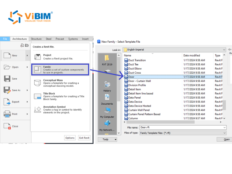
Step 1: Start with the Basics
Start your Revit Family Creation by choosing the right family template (here, the Door.rft template), then build a skeleton of named reference planes that drive the door’s width and height. The template locks in the family’s category and hosting behavior, so the right pick upfront saves a full rebuild later.
Pick the template: Open File > New > Family and choose Door.rft (or Metric Door.rft) from the template list.
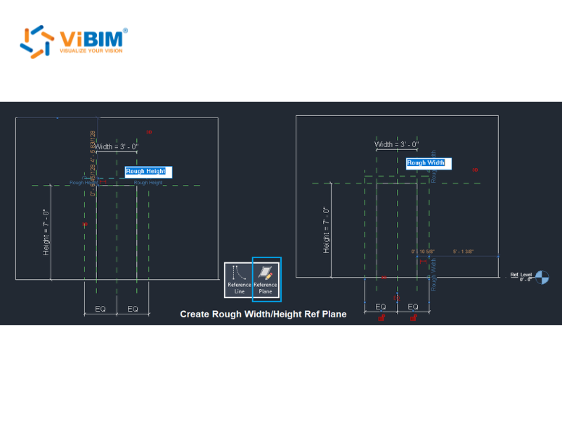
Build the reference-plane skeleton:
- In the floor plan, go to the Create tab and select the Reference Plane tool.
- Draw the Rough Width and Rough Height planes around the opening.
- On the Annotate tab, use Aligned Dimension to dimension them, then click EQ so they stay centered as the door flexes.
- Name every plane (Left, Right, Head, Sill) so geometry has something to lock onto.
From the floor: We pick the template by category so the door hosts and schedules correctly downstream. Get it wrong and the family fights you in every project it lands in.
With the skeleton set, you can model the door geometry.
Step 2: Model the Geometry
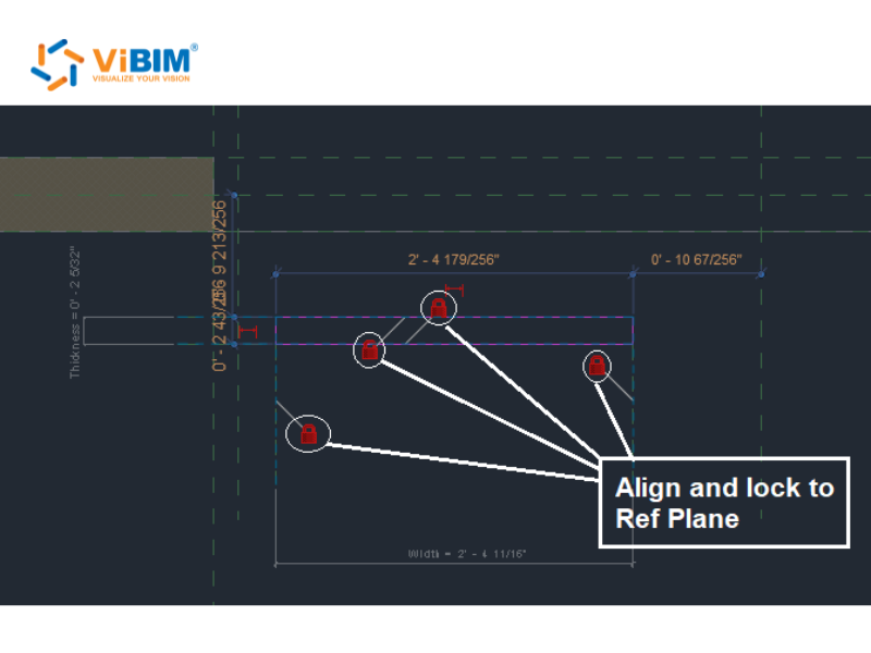
Model the door in three parts (the opening, the leaf, and the frame), locking every sketch line to the reference planes so the geometry flexes instead of breaking. Locked geometry is what separates a parametric family from a static block.
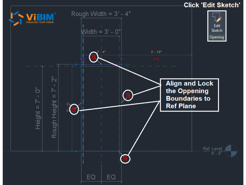
Cut the opening:
- On the Create tab, open the opening sketch (Edit Sketch).
- Align each of the four boundary lines to the Rough Width / Rough Height planes.
- Click the padlock on each line to lock it. Locked lines flex with the planes, unlocked ones drift.
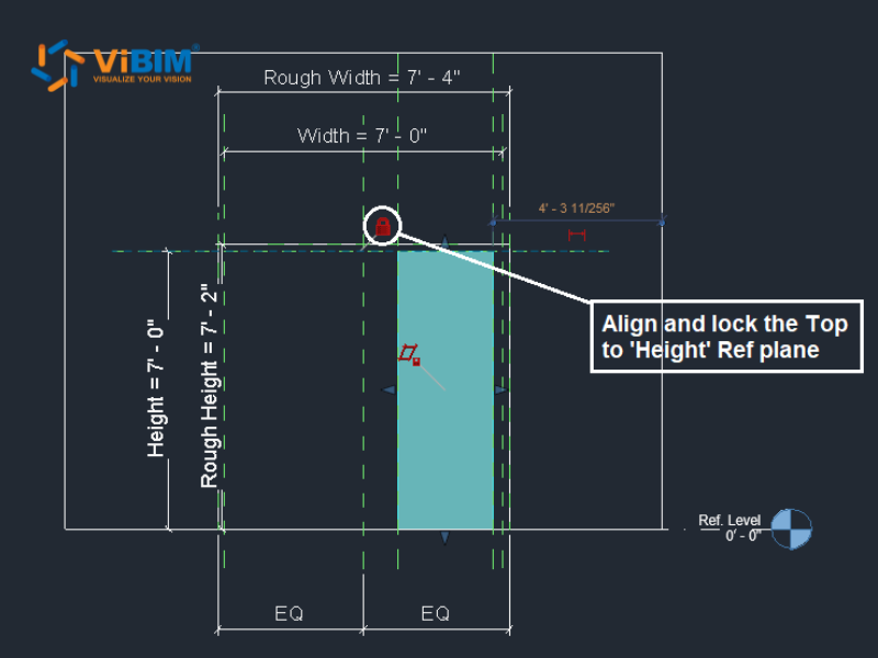
Model the leaf:
- On the Create tab, choose Extrusion and draw the leaf profile in plan.
- Lock the profile edges to the reference planes.
- In an Elevation view, drag the top of the extrusion to the Height plane and lock it.
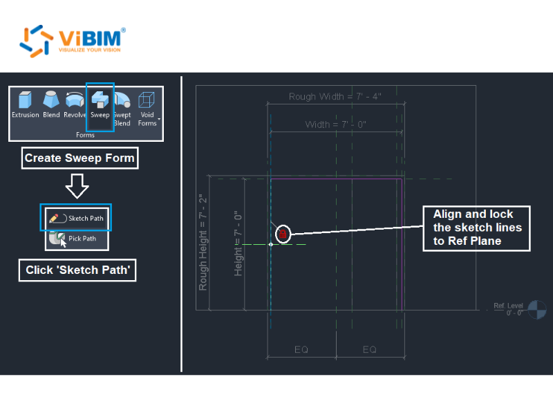
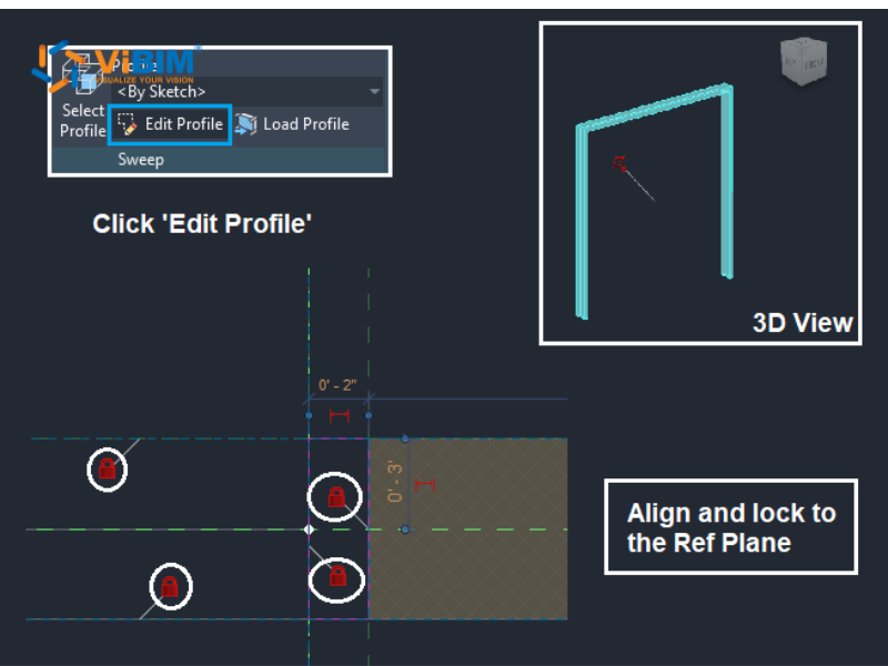
Add the frame:
- On the Create tab, choose Sweep, then Sketch Path.
- Draw the path around the opening and lock it to the rough-opening planes.
- Click Edit Profile, sketch the frame’s cross-section, and finish the sweep.
On site: We model the opening from the real wall’s point cloud, the way every point cloud to BIM job begins, at 3′-0″ × 7′-0″ (914 × 2134 mm), not a catalog size that may not fit the as-built condition. Where a solid can’t make the shape (a window reveal, an irregular opening), we cut it with a void form instead.
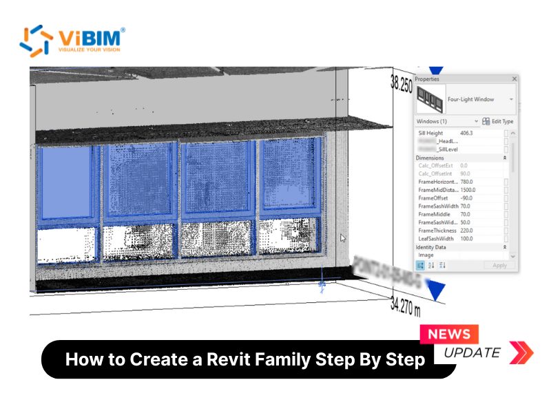
Step 3: Add Parameters and Formulas
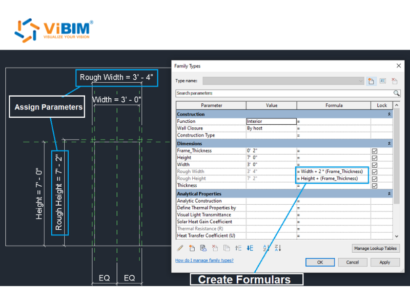
Turn the fixed dimensions into parameters, then drive the related sizes with formulas so the whole door updates from a couple of inputs. This is the step where a flat model becomes an intelligent Revit family.
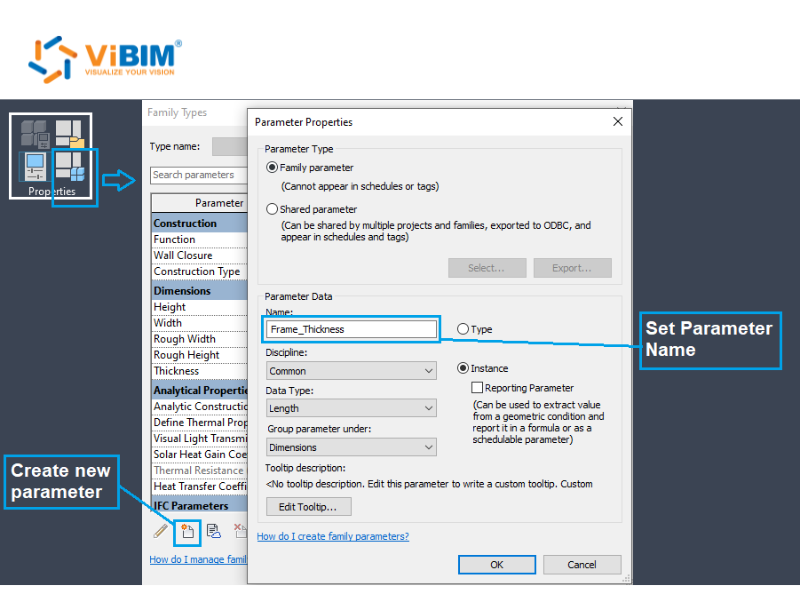
Create the parameter:
- Open the Family Types dialog and click New Parameter.
- Name it Frame_Thickness, set the discipline to Common and the type to Length, then give it a value of 2″ (51 mm).
Add the formulas:
- In the same dialog, set Rough Width = Width + 2 × (Frame_Thickness).
- Set Rough Height = Height + Frame_Thickness.
- Change the door’s Width and click Apply. The rough opening recalculates itself.
Why it matters: Formula-driven openings keep the door correct at any size, with no manual math and no drift between the leaf and the wall it sits in.

Step 4: Nest the Hardware
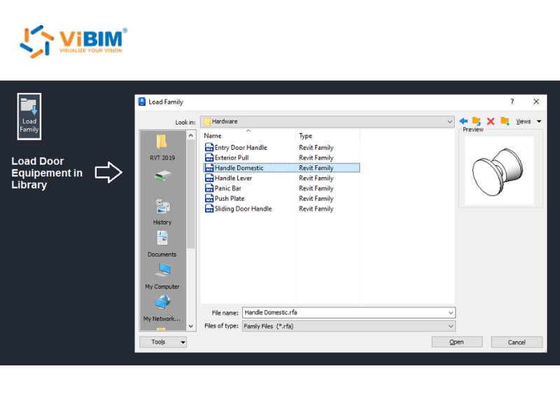
Load the door hardware as a nested family, then associate its parameters to the door so you control the handle from the door itself. Nesting keeps each part reusable instead of welding everything into one block.
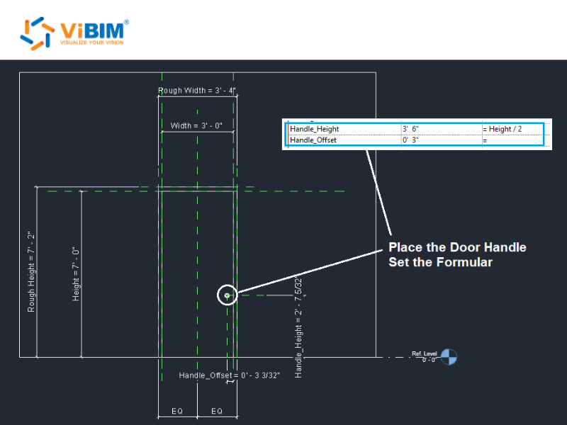
Load and place the handle:
- On the Insert tab, click Load Family and bring in the handle (here, Handle Domestic) from the hardware library.
- Place it on the leaf and align it to your reference planes.
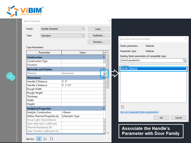
Wire its parameters to the door:
- Drive its position with a formula, Handle_Height = Height / 2, so it re-centers on any door size.
- Open the handle’s Type Properties, click the small associate button next to Handle_Material, and link it up to the parent door family.
In practice: Nesting hardware this way keeps our family library tidy and every component schedulable on its own line.
Step 5: Assign Materials and Preset Types
Assign material parameters, then create preset family types so one door file carries every size you need. This is the type creation step, and it’s where a single parametric door stands in for a whole schedule.
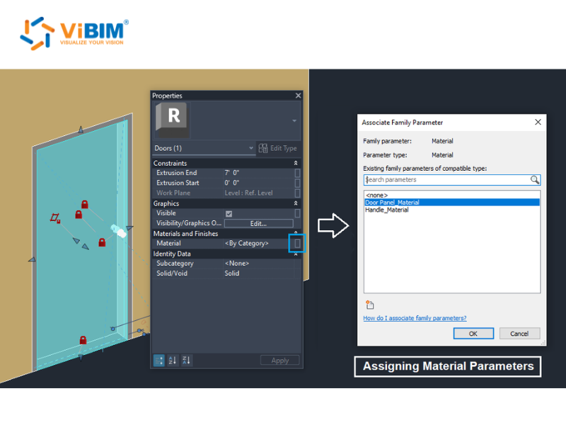
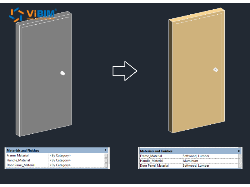
Assign materials:
- Select the geometry, then associate Door Panel_Material and Handle_Material to category.
- Set real materials (Softwood for the frame and panel, Aluminum for the handle) and turn on their render appearance.
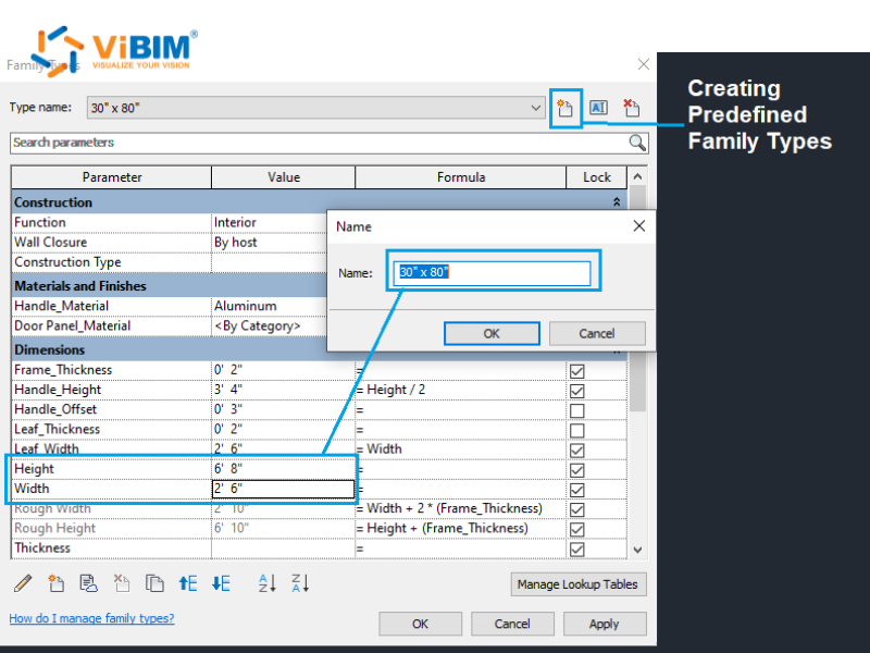
Create preset types:
- In Family Types, click New and name a type by size, such as 30″ × 80″ (762 × 2032 mm).
- Set its Width and Height, then repeat for each size you place often.
- Past six types, move them to a type catalog (.txt) to keep the file light.
Clean the preview: Hide the host wall in a 3D view, then choose Save As > Family, click Options, and set the clean 3D view as the thumbnail preview.
From production: Preset types cut placement time on large door schedules and stop modelers from rebuilding the same size twice.
Step 6: Test the Family in a Project
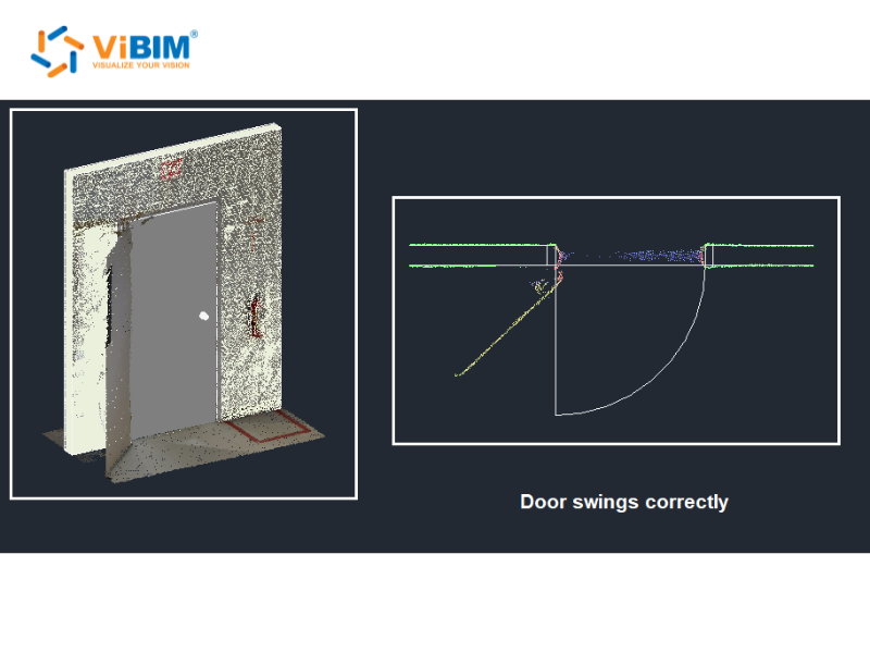
Load the finished door into the project, place it in the wall, and confirm it flexes, schedules, and swings correctly. Testing in context is the step most tutorials skip, and the one that catches the real problems.
- Save the .rfa, open a project, and use Load into Project.
- Host the door in the scanned wall and switch between your preset types to check each one resolves.
- Change an instance parameter and confirm the geometry flexes without breaking.
- In plan, verify the swing. The door has to clear the actual opening.
Our QC: We test the door against the original point cloud before sign-off. If the swing fouls a return wall in the real space, the model has to show it, not hide it.
The parameters you add in these steps behave in two ways, instance or type, and choosing correctly matters.
Revit Family Parameters: Instance vs Type
A Revit family parameter is either an instance parameter, which varies per placed element, or a type parameter, which is shared by every element of that type. Choosing the right scope controls how the family flexes and how it reports in schedules, so it’s a decision worth getting right early in Revit family creation. The difference comes down to scope.
| Aspect | Instance parameter | Type parameter |
| Scope | Per placed instance | All instances of a type |
| Edited in | Properties palette | Edit Type |
| Example | Mounting height of one light fixture | Door width, 36″ (914 mm) |
A handy rule: if two placed elements should be able to differ, make it an instance parameter; if they should always match, make it a type parameter. This is also where type creation in a family comes in. When you need several fixed sizes of the same door family, you create them as types (or, past six, as a type catalog .txt). Get the scope wrong and the family either won’t flex when it should, or it flexes when it shouldn’t.
Once parameters and types are mastered, advanced techniques scale Revit family creation further.
What Are Advanced Revit Family Creation Techniques?
Advanced family creation covers four techniques that scale families beyond a single object: nested and shared families, parametric formulas and constraints, visibility and detail control, and Dynamo or API automation. Each one extends a basic family into something that holds more data, adapts to more conditions, or builds at volume.
Nested & Shared Families
Nested families are families placed inside another family; shared families let those nested components schedule and tag independently. The door we built earlier nests a handle inside the door family, and that’s a nested family. Make that handle shared, and it can report on its own schedule line and carry its own tag, instead of disappearing into the host. Shared parameters, defined in an external .txt file, are what let that data stay consistent across every family and project.
Parametric Formulas & Constraints
Parametric formulas drive a family’s geometry from its parameters: for example if(Length > 1500 mm, 3, 2) to add a third support leg once a length passes 1500 mm (59 in). Formulas turn a family into a rules engine: change one input and the geometry responds. Constraints back them up, locking geometry to reference planes so nothing distorts when the family flexes. Together they’re the core of intelligent Revit family creation.
Visibility Parameters & Detail Control
Visibility parameters are Yes/No parameters that switch parts of a family on or off: the main way to control its detail level (LOD) across views. Set the coarse geometry, like a simple box, to show in Coarse views, and the fully detailed parts to show only in Fine. Subcategories add a second layer, giving each part its own line weight and graphic control. This is how one door family stays light in an overview and complete in the coordination BIM model.
Automation with Dynamo & the Revit API
Dynamo and the Revit API automate repetitive family work at scale. When you’re producing hundreds of families, doing each one by hand doesn’t hold up. At ViBIM, we use a proprietary in-house tool to auto-convert in-place elements into loadable families, which handles large-volume model conversions at speed without losing accuracy. That’s creating Revit families as a production line, not a one-off.
Powerful as these are, families only pay off when they’re built well, which is why getting them right matters.
Why Are Custom Revit Families Important?
Custom Revit families matter because they turn a generic model into an accurate, data-rich digital twin that drives coordination, scheduling, and reliable documentation. The value comes from one fact: a family carries both geometry and data, so getting Revit family creation right pays off across the whole project. Capturing that intelligence in the model, not just the drawing, is one of the core advantages of Revit software over generic CAD. These benefits follow directly from that.
- Accurate as-built geometry. Families modeled from a point cloud match the building as it actually stands, not as old drawings assume.
- LOD/LOI compliance. Dimensions, materials, and classification embedded in the family let the model hit the required Level of Development and information.
- Correct categorization. A door modeled as a Door, not a generic blob, means schedules, filters, and clash detection actually work.
- Reusability and standardization. One well-built loadable family carries a company’s standards into every project that loads it.
- Lighter model performance. Families built to the right level of detail keep the file fast instead of bloated.
These benefits only hold when families are built correctly, and several mistakes routinely undermine them.
Common Revit Family Creation Mistakes (From 1,000+ Projects)
The most common Revit family creation mistake is assigning the wrong category, which silently breaks schedules, filters, and clash detection downstream. Across more than 1,000 projects, our QC team flags the same issues again and again. Creating Revit families that hold up on site means designing these out from the start.
- Wrong category or host. A door modeled as a generic model won’t behave in views or schedules. Fix: start from the correct template so the category is right from the first click.
- Over-modeling beyond the LOD. Every bolt and weld modeled in detail bloats the file and slows the project. Fix: model only to the level of development the deliverable needs.
- Inconsistent naming and no shared parameter file. Names like “L,” “W,” “H” and one-off parameters wreck cross-discipline schedules. Fix: use a naming convention and a shared parameter file.
- Hard-coded dimensions. Geometry typed in by hand won’t flex. Fix: drive every key dimension with a parameter, the way we drove the rough opening with a formula earlier.
- Skipping the flex test. Constraints that look fine often break when the size changes. Fix: flex the family through its range before delivery, never after.
- Ignoring tolerance to the scan. A family that drifts from the point cloud no longer matches the as-built reality. Fix: check geometry against the original scan, the way we verify a door’s swing before sign-off.
Avoiding every one of these comes down to a single discipline: building to defined project standards.
How Do You Ensure Revit Families Meet Project Standards?
Reliable Revit family creation comes from working to defined standards: naming, parameters, geometry tolerance, and information delivery. A family can look fine on its own and still break the moment it joins a coordinated model. Five controls keep every ViBIM family consistent:
- Naming conventions and a shared parameter file: so parameters schedule and tag the same way across every discipline.
- LOD and LOI to spec: geometry and data modeled to the exact level of development and information the deliverable calls for.
- Geometry tolerance against the point cloud: each family checked back to the scan so it matches the as-built reality, not a nominal size.
- Two-layer independent QA/QC: every model passes two separate quality checks before it ships, the step that catches drift before a client ever sees it.
- Compliance with recognized standards: ISO 19650, PAS 1192, AIA E202/E203, and the BIMForum LOD Specification.
Meeting these standards in-house takes time and expertise, which raises the build-versus-outsource question, especially for Scan to BIM Revit services.
When Should You Outsource Revit Family Creation?
Outsource Revit family creation when volume, complexity, or point-cloud accuracy outpace your in-house capacity, and keep the simple, repeatable families in-house. The line isn’t about skill; it’s about where your modelers’ hours pay off most. Outsourcing makes sense when:
- The library is large or the deadline is tight: hundreds of families, or a project that can’t wait for them.
- Families come from a point cloud: as-built doors, windows, and MEP that have to match a scan within tolerance.
- The work spans MEP or structural disciplines: families that must carry connectors, structural behavior, and cross-discipline standards.
One question the firms we work with ask first: “Can you match our naming standard?” That consistency is exactly what an outsourcing partner should guarantee. Across more than 1,000 projects, our Revit Family Creation service holds a 99% on-time record, with turnaround up to 30% faster than the in-house average.
Still deciding? These common questions cover the rest.
Revit Family Creation FAQs
What is the difference between a Revit family and a Revit project?
A Revit family is a single component (a door, a window, a light fixture) with its own parameters and geometry, saved on its own. A Revit project (.rvt) is the whole building model that loads and arranges those families. In short, a project is a collection of families.
What’s the difference between .rfa and .rvt files?
An .rfa file is a loadable Revit family you build in the Family Editor and load into projects. An .rvt file is the Revit project itself. You create families as .rfa, then place them inside the .rvt model.
Can you create a Revit family from a DWG or CAD file?
Yes. Import the DWG into the Family Editor and use it as an underlay to trace, then model the family natively in Revit. Lock your reference planes to the imported linework, build the solid forms over it, and delete the import once the family is parametric. Leaving raw DWG geometry inside the family is a mistake: it bloats the file and won’t flex like native Revit geometry.
What are the 3 types of Revit families?
Revit families come in three types: system families (built into Revit, like walls and floors), loadable families (made in the Family Editor and saved as .rfa, like doors and windows), and in-place families (created inside one project for a single, unique element).
How do you create a new family type in Revit?
You don’t need the Family Editor. In the project, select the family, click Edit Type > Duplicate, name the new type, then change its parameter values, such as a new door width. The type then lives in that project.
Are Revit families free?
Some are. Revit ships with built-in system families and a starter library, and manufacturers and BIM content libraries offer free, ready-made loadable families. Custom families built to a project’s exact standards, though, are usually made in-house or outsourced.
Instance vs type parameter: which should I use?
Use an instance parameter when placed elements should differ from each other, like a light fixture’s mounting height. Use a type parameter when every element of that type should match, like a door’s width. If in doubt, ask whether two placed copies should ever differ.
From Template to Finished Family
Revit family creation runs from knowing what a family is, through the six-step build, to judging when a job is better outsourced than built in-house. Get the fundamentals right (the correct template, locked geometry, parameters that flex, and standards that hold) and one well-built family carries accurate data across the whole project.
When the volume or the point-cloud accuracy outgrows your team, ViBIM’s Revit BIM Modeling services take it from scan to schedule-ready model.