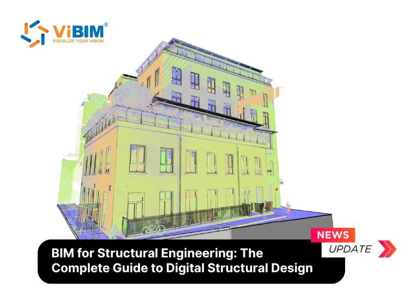
BIM for architects is a model-based design process in which intelligent building objects connect geometry and information to plans, sections, schedules, and coordinated model outputs. The workflow develops across four project stages, from concept design to construction handover, so design decisions stay tied to connected documentation. BIM benefits for architects come from controlled revisions and cross-discipline coordination rather than from 3D visualization alone. Before issue, the model’s geometry, information, and exchange outputs must be validated, including the existing-condition source used for renovation projects.
The sections below then cover how architects collaborate on a shared model, choose software against delivery requirements, and decide when to implement BIM in-house or outsource the modeling.

What Is BIM for Architects?
BIM for architects is a workflow for creating and managing intelligent building objects whose geometry and information feed connected views, schedules, and drawing sheets. A wall object carries a defined location, thickness, composition, and relationship to hosted elements such as doors and windows instead of existing only as two plan lines.
BIM for architecture practices centers on the decisions an architect owns: spatial planning, circulation, envelope design, material intent, room requirements, clearances, and architectural documentation. Structural and MEP models carry different systems, but their grids, openings, shafts, ceiling zones, and service routes must coordinate with the architectural model.
Four working layers connect the design model to the documents an architect issues:
- Parametric geometry. Walls, floors, roofs, rooms, doors, and windows have dimensions and relationships that the model can maintain when a design changes.
- Required information. Materials, classifications, fire ratings, room data, and other parameters are added when the project brief or model use requires them.
- Derived documentation. Plans, sections, elevations, tags, and schedules read from modeled objects instead of being maintained as unrelated drawings.
- Shared project references. Coordinates, linked discipline models, file versions, and exchange requirements establish how the architectural model relates to the rest of the project.
A model change reaches only the outputs that are correctly associated with it. Moving a modeled door can update its plan location and schedule entry, for example, but detached details, manual text, and incorrect parameters still need separate review. Building information modeling reduces repeated drafting through connected information, while model and drawing checks remain necessary before issue.
Architectural BIM vs. Traditional CAD Drafting
The difference between architectural BIM and traditional CAD is that CAD represents a design mainly with drawing geometry, while BIM uses building objects that can support several connected outputs. The practical gain is controlled change propagation, not the disappearance of 2D documentation.
The comparison below shows how each approach affects an architecture team:
| Aspect | Traditional CAD | Architectural BIM | Architect Implication |
| Representation | Lines, arcs, hatches, and drawing references | Building objects with geometry and assigned information | The model can distinguish a wall from a line that outlines it |
| Design changes | Each affected drawing must be found and revised | Associated views and schedules can update from the changed object | Fewer manual updates are needed, but every affected output still requires review |
| Documentation | Plans, sections, elevations, and schedules may be maintained separately | Multiple documents can derive from the same model state | Model errors can also spread into several outputs if they are not caught |
| Coordination | Teams compare drawings or referenced files | Teams can link or federate discipline models and run interface checks | BIM reveals more coordination candidates, while people still assign and resolve each issue |
| Exchange | DWG, PDF, and other drawing-based packages | Native models, IFC, DWG, PDF, and data schedules as required | The contract must define the format, version, coordinates, and permitted use |
A disciplined CAD set can be accurate, and a poorly structured BIM model can still produce inconsistent documents. BIM changes how information is created, connected, and checked. Model and document connections become useful in different ways as a project moves from feasibility to handover.

How Do Architects Use BIM Across a Project?
Architects use BIM to compare options during concept design, coordinate building interfaces during design development, produce connected documents, and manage current information through construction and handover. Across a project, BIM for architects supports a different decision at each stage, so its geometry and information should develop in response to agreed uses rather than grow for their own sake.
Each stage follows the same working sequence: the architect makes a decision, the team updates the model, and the project receives a defined output or check.
Concept Design and Feasibility
During concept design, architects use a low-detail BIM model to compare massing, program, area, and site-response options before committing to detailed assemblies. The model can test whether the required spaces fit the site, how alternative building volumes affect usable area, and how orientation changes early daylight or energy assumptions.
At this stage, comparison matters more than precision. A model may represent the building as a single mass at LOD 100, which the BIMForum LOD Specification defines through approximate or derived information rather than element-specific geometry. The output is a documented option and its assumptions, not a coordinated construction model or certified performance result.
Design Development and Coordination
During design development, architects refine spatial and envelope decisions while coordinating the architectural model with structural and MEP references. Room adjacencies, ceiling heights, façade proportions, materials, and circulation become measurable design conditions. Linked models then expose where beams, ducts, shafts, risers, openings, and service zones affect that intent.
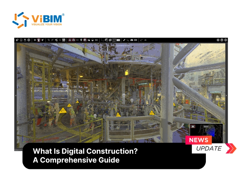
Existing-building projects need a different starting point. Renovation and retrofit design should begin with an approved existing-condition source rather than assumed geometry. The Scan to BIM process can use a registered point cloud, meaning scan data aligned into one project coordinate system, to support a scoped base model where the survey coverage, point density, tolerance, and required model elements have been agreed.
The design-development output is a coordinated architectural model with an open issue list. A coordinated model is not a “clash-free” file. The project team still has to assign each interface, resolve it, and record any accepted exception before documentation advances.
Construction Documentation
During construction documentation, architects use the model to generate and maintain plans, sections, elevations, schedules, and sheets from a connected design source. Precise 2D technical drawings and detailed 3D building geometry can then represent the same approved design state instead of developing as separate records.
A modeled change can update its associated outputs. Moving a door can change the plan, elevation, room relationship, tag, and door schedule when those items reference the same object. Autodesk Revit supports project sheets, drawings, schedules, and centrally shared work.
Connected does not mean automatic in every case. Imported details, manual annotations, view-specific overrides, broken tags, and incomplete parameters can remain out of sync. Architects issue coordinated building documentation and construction sets only after reviewing both the model and its derived sheets.
Construction Administration and Handover
During construction and handover, architects use BIM to review project issues in model context and assemble current information for the owner under the responsibilities defined in the contract. The model can locate an RFI, compare an approved revision with an issued view, and help the team identify which package or model version governed a decision.
Handover requirements vary. A design model records design intent, while a record or as-built model reflects changes captured through the agreed project process. LOD 500 is not the automatic next stage after LOD 400. BIMForum relates LOD 500 to field verification and does not treat it as a progressively more detailed design level.
An existing-building or handover model supports future renovation only to the extent that its geometry and information were observed, updated, and checked. When verified records are prepared for operations, Scan to BIM for FM becomes a separate owner-side use case rather than an automatic outcome of every architectural model. That condition leads to the central business question for an architecture practice: what does BIM improve, and which mechanism produces each gain?
What Are the BIM Benefits for Architects?
The main BIM benefits for architects are clearer design decisions, fewer coordination and documentation inconsistencies, faster controlled revisions, earlier analytical feedback, and a more reliable base for existing-building work. A 3D model alone does not create those outcomes. The value of BIM for architects depends on how the model connects an architectural task to information that the project team can review and use. BIM is now a baseline in architectural practice, and the AIA 2024 Firm Survey Report records BIM use on billable projects rising to 52% at small firms, up from 37% in 2019, so the practical question shifts from whether to adopt BIM to which benefits are real and how each is produced.
Architect-owned outcomes differ from the wider benefits of BIM for contractors, owners, and facility teams, which belong to other parts of the project lifecycle.
Clearer Design Options and Client Decisions
BIM helps architects compare spatial, material, and performance options in one model before those choices are fixed in detailed documentation. A massing change can be viewed in plan, section, elevation, and 3D while the team compares area, daylight, envelope, or circulation effects against the same geometry.
The model gives the architect and client a common object to review. A client can see how a lowered ceiling affects the lobby volume, for example, while the architect checks the related section and room requirements. The output is a documented design choice with visible assumptions, not a promise that a rendering or early simulation represents final construction performance. Where a client needs to experience scale rather than read it, the same model can drive a BIM and virtual reality walkthrough.
Fewer Coordination and Documentation Errors
BIM can reduce coordination and documentation errors by exposing discipline interfaces and keeping associated views tied to the current model state. Coordination errors and documentation errors are separate classes. A duct crossing a beam is an interface problem. A door schedule that no longer matches the plan is a documentation problem.
In a buildingSMART International survey, respondents ranked 2D/3D design coordination (85%) and clash detection and quality checks (72%) as the processes BIM most optimizes. Linked or federated models let the team test geometry and clearances before construction. Associated plans, sections, tags, and schedules help the architect find stale outputs after a design change. Automated checks identify candidates, not final answers. The team must review false positives, assign each issue, resolve the design condition, and record any accepted exception.
Faster Revisions and Drawing Production
BIM speeds controlled revisions when a modeled change updates the plans, sections, elevations, tags, and schedules associated with that object. Changing a wall assembly, for example, can update its plan thickness, section build-up, material takeoff, and room-area boundary without redrawing each view from the beginning.
The time saving depends on model structure. View-specific overrides, detached details, imported drawings, manual notes, and incorrect object parameters can remain unchanged. Architects still review the affected sheet set, but connected outputs reduce the number of independent revisions that the team has to locate and recreate.
Earlier Performance and Quantity Feedback
A structured BIM model can give architects earlier feedback on daylight, energy, area, and material quantities while design options remain open. Model geometry supplies inputs for spatial or performance analysis, while object classifications and dimensions support schedules and quantity reports.
An architect can compare glazing ratios before the façade is documented or check how a floor-finish change affects scheduled area. Early results support design discussions with the client, cost consultant, and specialist engineer. The architectural model does not replace certified energy analysis, formal cost planning, agreed measurement rules, or the professional responsible for each assessment.

More Reliable Existing-Condition Design
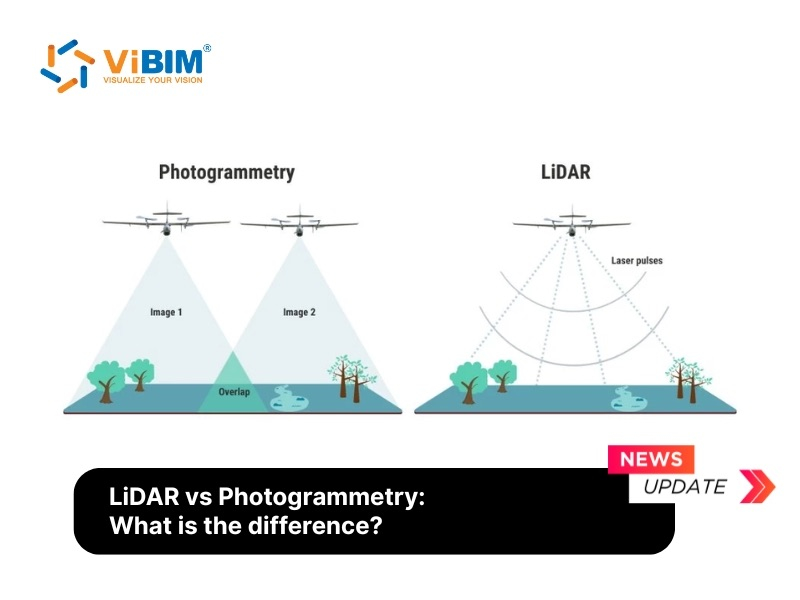
For renovation and retrofit, BIM gives architects a more reliable design base when the existing-condition model is built and checked against an approved survey or registered point cloud. Reality-capture data records visible site geometry, while an architectural Scan to BIM service can turn that evidence into scoped walls, floors, roofs, openings, rooms, and other objects the architect can use.
The reliability of that base depends on six agreed inputs:
- Survey coverage. The capture must include the areas and elements that affect the planned design.
- Registration quality. Individual scans must align within the project coordinate system before modeling begins.
- Required tolerance. The team must state how closely critical geometry should match the approved source.
- Visible evidence. Occluded, concealed, reflective, or inaccessible conditions remain limitations unless another source records them.
- LOD and LOI. Geometry and non-graphical information should match the intended model use instead of defaulting to the highest available detail.
- Deliverables. Required models, sheets, coordinates, file formats, and exclusions must be defined before acceptance.
A point cloud does not make every modeled element accurate by default. The project still needs checks that connect source evidence, modeled geometry, required information, and issued documents. Model validation provides that connection.
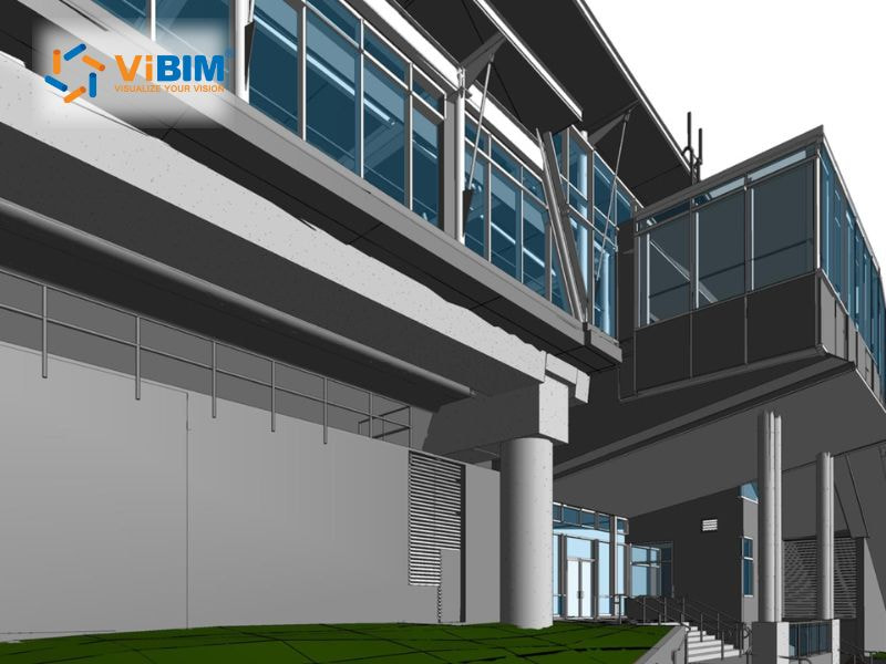
How Do Architects Validate a BIM Model Before Issue?
Architects validate a BIM model before issue by checking its geometry, required information, discipline interfaces, documentation consistency, and final exchange package. BIM validation for architects is evidence that a model is ready for an agreed use. Validation is not one software command or a universal pass score.
In practice, BIM for architects requires each check to have a named owner and acceptance basis. Responsibility follows the BIM Execution Plan, contract, and discipline ownership. The architect signs off architectural outputs within that agreed role rather than accepting responsibility for every object in a federated model.
The validation layers and their expected evidence are summarized below:
| Validation Layer | Architect Checks | Failure Prevented | Evidence or Status |
| Geometry and existing conditions | Levels, grids, boundaries, openings, clearances, dimensions, and source alignment | Design based on incorrect spatial assumptions | Check record with tolerance and exceptions |
| Information and documentation | Required parameters, tags, schedules, views, sheets, and revision state | Incomplete data or mismatched model and drawings | Completeness report and sheet-review status |
| Coordination and clearances | Linked models, coordinates, clashes, penetrations, and spatial allowances | Unresolved interfaces reaching construction | Issue register with owner and status |
| Exchange and issue readiness | File opening, units, coordinates, links, exports, naming, and permissions | Broken packages or lost information at handoff | Signed issue check and known-exception list |
Check Geometry and Existing Conditions
Geometry validation checks that the model’s levels, grids, boundaries, openings, clearances, and critical dimensions match the approved design or existing-condition source. The check must use the project’s units, coordinate system, tolerance, and source-reference version. “Accurate” has no testable meaning until those conditions are stated.
The geometry review should cover the following project-critical items:
- Primary references. Confirm levels, grids, project origin, shared coordinates, and units before checking individual elements.
- Architectural boundaries. Review room limits, wall locations, floor edges, openings, stairs, headroom, and the clearances defined by the brief.
- Existing conditions. Compare critical geometry with the registered point cloud or approved survey and record the locations used for spot checks.
- Source gaps. Mark occluded, concealed, unscanned, or low-density areas instead of modeling them as verified conditions.
The output is a geometry check record with measured exceptions, not a general statement that the model matches the site.
Check Information and Documentation Consistency
Information and documentation validation confirms that required parameters are complete and that tags, schedules, views, and sheets represent the current model state. The review starts from the project’s information requirements, not from every field the authoring software can store.
The reviewer checks naming and classification, required materials and properties, room and opening data, tag-to-object relationships, schedule filters, sheet references, revision status, and missing or duplicated outputs. A generated schedule proves only that the software can display the entered data. The values and filters still need review.
ISO 19650-1 describes a framework for organizing, exchanging, recording, versioning, and managing project information. Those information-management controls do not certify the geometric accuracy of a model.
Check Coordination and Clearances
Coordination validation checks linked discipline models, shared coordinates, physical clashes, required clearances, penetrations, and unresolved interfaces. A hard clash places two objects in the same space. A clearance check tests the working space needed around elements such as access panels, doors, equipment, and service zones.
A coordination check is complete only when it records:
- the model and version used for each discipline.
- whether every required link loaded in the agreed coordinates.
- the issue location, type, owner, due status, and proposed response.
- false positives and accepted exceptions with their reasons.
- the result of the rerun after the model changes.
Automated checking produces issue candidates. The architect and other discipline leads still classify each result, protect required spaces, assign responsibility, and confirm the agreed resolution.
Check Exchange and Issue Readiness
Exchange validation confirms that the issued RVT, IFC, DWG, PDF, or CDE package opens correctly, preserves the required coordinates and information, and carries the approved name, version, and status. Only the formats required by the brief belong in the test.
Before issue, test the following parts of the exchange package:
- reload referenced files and confirm that no required link is missing.
- check units, origin, coordinates, naming, revision, and suitability status.
- export and reopen the required RVT, IFC, or DWG deliverable.
- compare critical objects and properties with the authoring model.
- verify CDE permissions, transmittal contents, and known exceptions.
Industry Foundation Classes (IFC) is an open international standard for sharing built-asset data, as defined by buildingSMART. An IFC export is still a translation. The team must specify the schema and exchange requirement, then check what the receiving application can read.
A signed check record confirms which tests passed and which exceptions remain. The record does not certify an error-free model. Many of these controls depend on how people share files, permissions, and responsibility across the project.
How Do Architects Collaborate in BIM?
Architects collaborate in BIM through three separate mechanisms: co-authoring within one authoring environment, linked or federated coordination across discipline models, and controlled information exchange through a common data environment. At team level, BIM for architects works only when those mechanisms retain clear file ownership, version status, and approval responsibility.
The three collaboration modes should be evaluated separately:
- Co-authoring. Multiple architects edit the same project through worksharing, Teamwork, Project Sharing, or another multiuser environment. Ownership, permissions, synchronization, and element checkout rules control who can change which content.
- Linked or federated coordination. Architecture, structure, and MEP retain separate discipline models. The team references them together to review coordinates, interfaces, clearances, and issues without transferring authorship of every element.
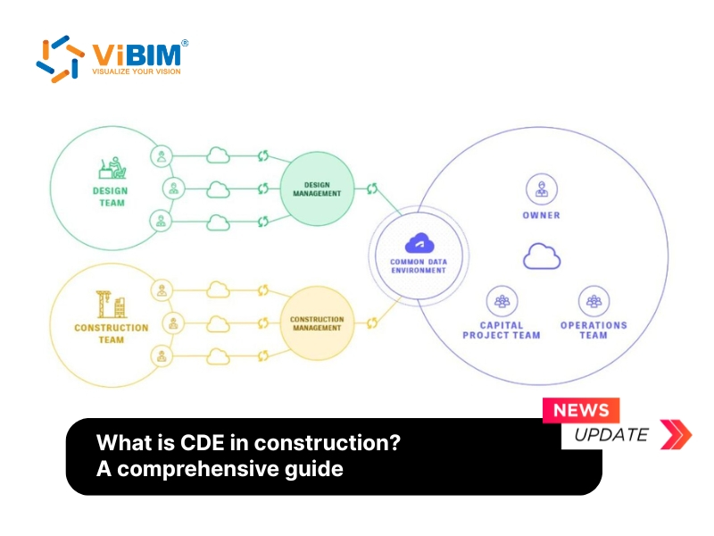
- Common data environment. A CDE controls file versions, suitability status, permissions, issue records, and formal exchanges. ISO 19650-1 describes information management through processes for exchanging, recording, versioning, and organizing project information.
Platform capability is only one part of co-authoring. Revit supports worksharing through a centrally shared model, Graphisoft offers BIMcloud-based collaboration through Archicad Collaborate, and Vectorworks uses Project Sharing as its multiuser environment. Model stability with several editors still depends on file size, model health, network or cloud conditions, permissions, linked content, and team standards. Simultaneous access does not make every visible file approved or current.
BIM objects affect collaboration as well. A shared object library needs controlled names, parameters, classifications, and versions so a door, wall type, or room object carries the same expected information across the project. More objects do not create a better architectural BIM workflow when their data or ownership rules conflict.
Once a firm separates co-authoring, federation, and information management, software selection becomes a requirements decision rather than a popularity contest.
Best BIM Software for Architects
The best BIM software for an architecture firm is the platform that supports its required combination of design authoring, connected 2D and 3D documentation, co-authoring, model scale, object standards, consultant exchange, and contractual deliverables. No platform wins every project type, consultant environment, and production method.
The four platforms should be compared against the firm’s actual delivery requirements, including the differences between Revit and Archicad that affect documentation output:
| Platform | Architect and Documentation Fit | Collaboration Approach | Exchange Support | What to Test Before Choosing |
| Autodesk Revit | Parametric building authoring with plans, sections, schedules, and sheets connected to the project model | Worksharing through a centrally shared model, with cloud workflows available in the Autodesk environment | Native RVT plus required IFC, DWG, and other project outputs | A representative construction set, consultant links, family standards, sync behavior, and model performance |
| Graphisoft Archicad | Architectural authoring and documentation with model views, layouts, schedules, and object libraries | Teamwork and BIMcloud-based collaboration for distributed project teams | Native PLN plus IFC and the firm’s required consultant formats | Several architects editing one test project, object-library control, consultant exchange, and recovery procedures |
| OpenBuildings Designer | Building design, visualization, documentation, and simulation for architecture and engineering workflows | Collaboration method should be tested against the firm’s Bentley environment and project setup rather than assumed from the authoring tool | Confirm the required native, IFC, DWG, and reference-model workflow with every receiving discipline | A large representative model, referenced disciplines, drawing production, required exports, and downstream file opening |
| Vectorworks Architect | Integrated 2D drawing, 3D modeling, architectural documentation, and openBIM workflows | Project Sharing provides a multiuser environment for the architectural team | IFC, RVT, DWG, and other supported exchanges should be tested against project requirements | Project Sharing, graphic standards, object data, consultant imports, and the issued sheet package |
The table protects two requirements that are often separated during software selection. Architects need precise 2D technical drawings alongside detailed 3D building models, and both outputs must remain usable when several people edit, reference, review, and exchange the project.
Use a pilot file before choosing or changing a platform. The pilot should contain a representative model area, linked consultant information, a sheet package, the firm’s object library, and at least one required export. Test completion speed, file behavior, information loss, drawing quality, and issue recovery with the people who will run the workflow.
A deeper building information modeling software comparison can cover feature breadth. For an architecture practice, the decision starts with the construction set and exchange requirements the firm is contracted to deliver. Choosing the tool solves only one part of adoption. Standards, responsibilities, training, and validation determine whether the workflow holds together.
How Should an Architecture Firm Implement BIM?
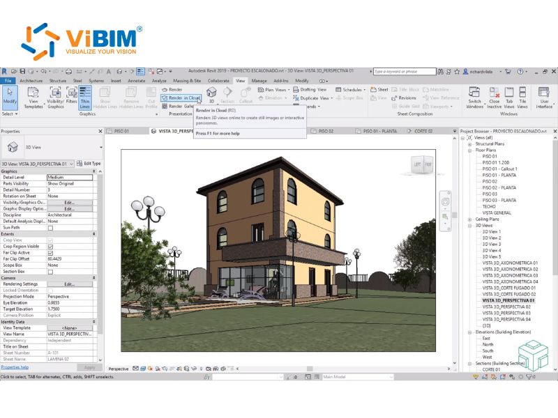
An architecture firm should implement BIM by defining its required uses and deliverables first, then setting responsibilities, preparing the working environment, piloting one bounded project, and scaling from measured lessons. An implementation plan makes BIM for architects a managed production workflow with defined design effort, information ownership, model standards, fees, training, hardware, and review.
A controlled BIM implementation can be organized into five steps:
- Define model uses and deliverables. Decide which decisions the model must support, such as option comparison, documentation, coordination, quantity feedback, or existing-condition design. Name the required model, sheets, schedules, formats, and issue milestones before selecting tools or detail.
- Set responsibilities and information rules. Create a BIM Execution Plan (BEP) that defines authorship, coordinates, LOD and LOI requirements, file structure, exchange method, model reliance, approval, and review. The ISO 19650 series supplies an information-management framework, but a standard cannot choose the project’s scope or responsibilities.
- Prepare the working environment. Configure templates, shared parameters, object libraries, naming, CDE permissions, model partitioning, backup, hardware, and consultant links. Training should cover these project workflows as well as authoring commands, because software skill alone does not control information quality.
- Run one bounded pilot. Choose a project or package with moderate complexity, a defined team, and measurable deliverables. Test co-authoring, documentation, consultant exchange, issue management, model size, and review without exposing the whole practice to an unproven process.
- Measure, correct, and scale. Review issue types, repeated rework, sheet consistency, exchange failures, model performance, staff capability, and time distribution across project stages. The firm should revise its standards and fee assumptions before applying the workflow to larger or more complex work.
The five steps place common adoption problems where they can be controlled. Training addresses the learning curve. A pilot exposes infrastructure and interoperability limits. The BEP makes model reliance and liability visible. Measurement shows whether design effort has moved earlier in the project and whether the fee structure still reflects that work.
An architecture firm does not have to internalize every production task at once. Any external scope, though, needs the same clarity about inputs, decisions, deliverables, and acceptance.
When Should Architects Outsource BIM Modeling?
Architects should consider outsourcing BIM modeling when a clearly bounded production or existing-condition scope exceeds internal capacity or requires a workflow the firm cannot support reliably in-house. Outsourcing can add modeling capacity or specialist production, but the architect retains design decisions, approvals, and professional responsibility as defined by the contract.
Four situations can justify an external modeling scope:
- a short-term production package would overload the internal team.
- a renovation project needs an architectural base model built from point-cloud data.
- the deliverable requires a defined LOD, LOI, family standard, sheet set, or exchange format that the firm cannot produce consistently.
- the project needs a separate production and model-review layer while design authority remains with the architect.
Before outsourcing, the architect should define the handoff and acceptance criteria:
- input files, registration status, survey coverage, and known data gaps.
- model disciplines, element scope, exclusions, tolerance, LOD, and LOI.
- coordinates, units, Revit version, families, parameters, and naming rules.
- required RVT, IFC, DWG, PDF, schedules, and sheets.
- review milestones, issue method, revision limits, and approval responsibility.
- evidence used for acceptance, such as model-to-source checks and sheet review.
How Does ViBIM Support Architectural BIM Delivery?
ViBIM supports architecture firms through three bounded deliverables: architectural Scan to BIM, as-built documentation, and BIM coordination support. Each scope begins with agreed inputs, model uses, outputs, and acceptance criteria.
The three deliverables address different production needs:
- Architectural Scan to BIM. ViBIM can use registered RCP, RCS, or E57 point-cloud data to model the building elements defined in the brief. The scope controls tolerance, LOD, LOI, exclusions, and whether delivery requires Revit, IFC, or DWG.
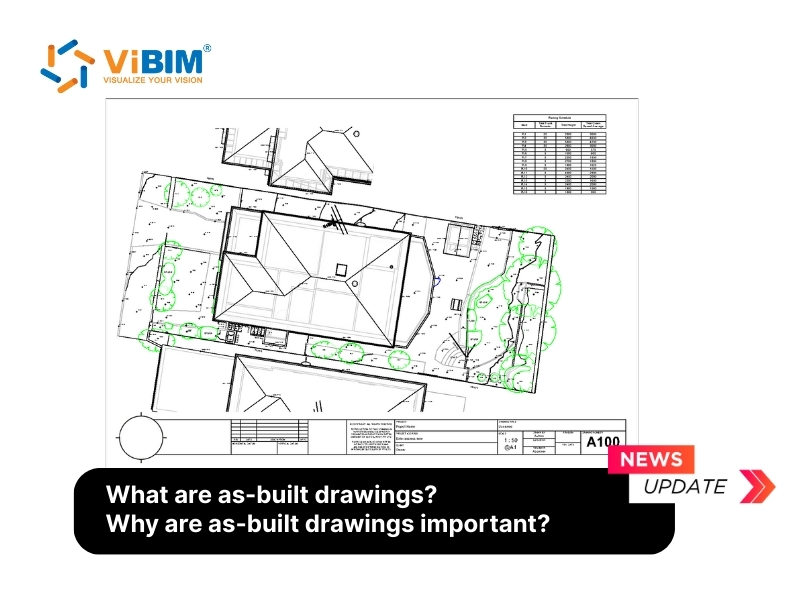
- As-Built Documentation. The team can extract floor plans, reflected ceiling plans, building sections, and elevations from the architectural model. Model-derived views reduce disconnected drafting, but the issued sheets still require annotation, reference, and consistency checks.
- BIM Coordination Support. Model cleanup, clash review, and multidisciplinary coordination can extend the architecture team’s production capacity. The architect retains design decisions, issue resolution, and final approval.
ViBIM’s 30+ team checks geometry, required parameters, deviations, missing elements, and data consistency through two independent QC layers. Its current company record reports a 99% on-time delivery rate on completed projects.
A bounded brief protects both sides of the handoff. The remaining scope questions concern the LOD architects typically use, whether BIM is mandatory, and how the workflow applies to existing buildings.
Frequently Asked Questions
The answers below clarify three BIM scope questions that depend on project requirements rather than on software capability alone.
What LOD Do Architects Typically Use?
Architects commonly work across LOD 100 to LOD 300 for concept through documented design, with LOD 350 used when the project requires defined interface geometry. The exact level depends on the agreed model uses, elements, and deliverables rather than one universal phase rule.
LOD 400 usually supports fabrication responsibility, while LOD 500 records field-verified existing or as-constructed conditions. One model can contain elements at different levels. The contract and BEP should define those requirements, and the BIM level of development specification should identify how far each element can be used.
Is BIM Mandatory for Architects?
No, BIM is not mandatory for every architect under one global rule. Requirements vary by jurisdiction, public client, project type, procurement route, and contract. A government or client mandate can require BIM for a defined project even when no general law applies to every architecture practice.
Architects should check the current project brief, appointment, information requirements, and relevant authority guidance before agreeing deliverables. The old labels or requirements used by one country should not be assumed to apply in another jurisdiction or to a private project.
Can BIM Be Used for Renovation and Existing Buildings?
Yes, BIM can support renovation and existing-building design when current conditions are captured, registered, modeled, and checked to an agreed scope and tolerance. The workflow can begin with an approved survey or reality-capture dataset, continue through a registered point cloud and scoped architectural model, and finish with validation before design use.
Point clouds are one source of existing-condition evidence, not the definition of BIM. Unscanned, concealed, inaccessible, reflective, or out-of-scope conditions remain exceptions unless another approved source records them.