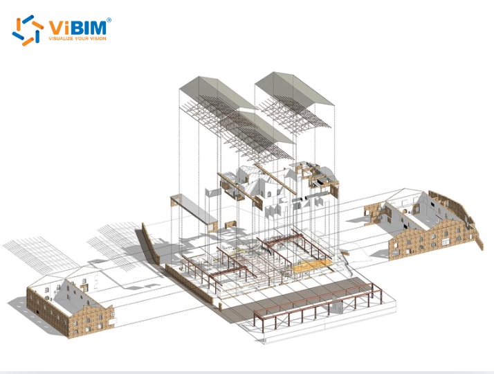
A 3D BIM model is a coordinated assembly of building objects that carry both geometric and non-geometric information. Every discipline on a project designs and documents from that assembly, then hands it over as a verifiable record of the building. A conventional 3D model may contain metadata, but it does not require the structured building objects and relationships used for BIM coordination and documentation.
The model supports three uses: clash detection before construction, coordinated drawings and quantities, and design review without authoring software. 3D BIM modeling produces that model in four stages, from preparing the source drawings or point cloud to federating and checking the combined result. How detailed it needs to be is set by the project stage rather than pushed as far as the software allows.
The delivery package contains four parts, from the native authoring file to the object data the scope requires, and five checks decide whether it is accepted. Agree those requirements before modeling starts; otherwise, a complete file package may still be unusable for the schedules, quantities, or asset queries the receiving team needs.
Four decisions sit outside the model itself: the Building Information Modeling software the work runs on, whether a ready-made model can stand in for a project-specific one, where the model falls short, and when the modeling is better outsourced than kept in-house.

What Is a 3D BIM Model?
A 3D BIM model is an intelligent, data-rich digital representation of a building or infrastructure asset created during the foundational 3D phase of the Building Information Modeling (BIM) process. Its elements are identifiable objects that store geometry, properties, and relationships rather than surfaces that show shape alone.
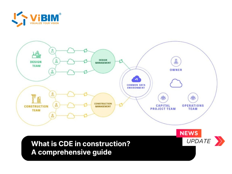
During 3D BIM modeling, teams create, manage, and share geometric and non-geometric information within a common data environment (CDE). The resulting model gives each project discipline a coordinated source for design review, clash detection, drawings, schedules, and quantities.
Project requirements determine which objects and properties the model must contain. This coordinated model provides the geometric and object-data foundation for four later BIM dimensions:
- 4D BIM links model objects to construction schedules and sequencing.
- 5D BIM connects quantities and cost data for estimating and cost control.
- 6D BIM adds energy and sustainability information for performance analysis.
- 7D BIM connects asset and maintenance data for facility operations.
These dimensions extend the coordinated 3D objects rather than replace the underlying model.
Can a 3D BIM Model Include Non Geometric Information?
Yes. BIM objects can store non-geometric information alongside their geometry. The agreed scope defines which properties must be populated; the software only provides the fields and tools used to manage them.
The model holds two kinds of information.
| What the file holds | Examples |
| Geometry | walls, floors, roofs, structural frame, ducts, pipes, conduit, equipment, openings, topography |
| Bound data | material, dimensions, product code, fire and acoustic ratings, classification code, and the relationships between objects |
That bound data falls into four groups.
- Product identity. Manufacturer, model reference, and the specification it was selected against.
- Performance values. Fire rating, U value, acoustic rating, load capacity.
- Spatial data. Room areas, heights, volumes, and the space an element sits in.
- Classification and status. Uniclass or Omniclass code, project phase, and whether an element is existing, new, or due for demolition.
On ViBIM Scan to BIM projects, a LOD 200 architectural, structural, and basic MEP scope may include equipment attributes taken from site photographs. An as-built marketing package can also include Office Area, Warehouse Area, Deck Height, Clear Height, Sprinklered, and Mechanical Area for extraction from the delivered model.
That information may not be visible in a rendered view. The distinction becomes clear when a user selects an element, checks its properties, or generates a schedule from the model.
What Is the Difference Between a 3D Model and a 3D BIM Model?
A conventional 3D model describes how something looks in three dimensions. A 3D BIM model also identifies what each building element is, stores its properties, and records relationships that support coordinated views, schedules, quantities, and checks. The two files can look similar on screen but behave differently when someone tries to use their contents.
The comparison below shows how those differences affect project use:
| Comparison point | Conventional 3D model | 3D BIM model |
| Basic structure | Surfaces, meshes, or solids | Building objects such as walls, doors, ducts, and equipment |
| Embedded information | Optional metadata, if added | Structured parameters defined by the project scope |
| Object relationships | Not required | Elements can relate to levels, rooms, systems, and other objects |
| Changes | Views may need separate updates | Connected views and schedules update from the same object |
| Project output | Visualization and geometric reference | Coordination, documentation, quantities, and model-based review |
A wall makes that difference concrete. In a plain 3D model, the wall may be only a surface or solid. In the BIM file, the software recognizes it as a wall object that can store thickness, material, fire rating, classification, and spatial relationships. Changing its thickness updates the connected plans, sections, elevations, and schedules.
At handover, select several elements from different disciplines. A usable BIM object should expose the properties required by the scope. A visualization mesh may import into Revit as one geometry block, limiting schedules, coordination, and object-level editing even when the building looks complete.
What Is a 3D BIM Model Used For?
The model is used to coordinate building systems, produce consistent drawings and quantities, and review spatial decisions before construction. These applications use the objects and geometry stored in the 3D layer. Scheduling, cost planning, sustainability analysis, and asset operations extend that foundation into later BIM dimensions.
A 3D BIM Model Catches Clashes Before They Reach Site
The model supports coordination by combining architectural, structural, and MEP files into one federated review model that teams can check for conflicts. A hard clash places two objects in the same space, such as a duct passing through a beam. A soft clash identifies insufficient clearance, such as a valve with less than 24 in (610 mm) of maintenance access.
The review team then separates design conflicts from modeling issues. An element on the wrong level, a duct assigned to the wrong system, or a duplicate object can create a clash without requiring a design change. Resolving both types before construction gives each discipline a coordinated geometry to work from.
3D BIM Produces Coordinated Drawings and Quantities
The model generates plans, sections, elevations, schedules, and quantity takeoffs from the same set of objects. Moving a wall changes the geometry and properties referenced by those outputs, so the related views and schedules can update together.
The 3D layer supplies measurable quantities such as door counts or concrete volume. Adding unit rates and cost calculations belongs to 5D, so a project scope should distinguish model quantities from cost planning.
Clients Can Review a 3D BIM Model Without Revit
A review version of the model lets clients inspect spaces, dimensions, and design issues without editing the authoring file. Browser-based visualization makes the geometry accessible to reviewers who do not use Revit and can reveal spatial problems that are difficult to read in a plan.
The review tools support three common actions:
- Walk it. Move through rooms and corridors at eye level.
- Measure and section. Cut anywhere and take a dimension without asking for a new drawing.
- Mark up. Attach a comment to an object so the note travels with the element rather than with a PDF page.
ViBIM publishes review models to Autodesk Construction Cloud and can provide Leica TrueView, Cintoo Cloud, or BIMcollab outputs when they match the client’s workflow. Project permissions let reviewers comment on the current version without changing the authoring model.

How Is a 3D BIM Model Created?
3D BIM modeling creates the model by preparing source information, setting up the project file, building objects by discipline, and checking the combined result. A new-building model starts from design drawings and specifications. An existing-building model starts from measured survey data, usually a registered point cloud.
The creation workflow has four stages:
- Prepare the source. Confirm the current design package for a new building or register the survey data for an existing one.
- Set up the project. Establish levels, grids, coordinates, naming conventions, and required parameters before creating objects.
- Model by discipline. Build architectural, structural, and MEP objects in coordinated discipline files.
- Federate and check. Combine the discipline models, review their alignment and data, and resolve issues before delivery.
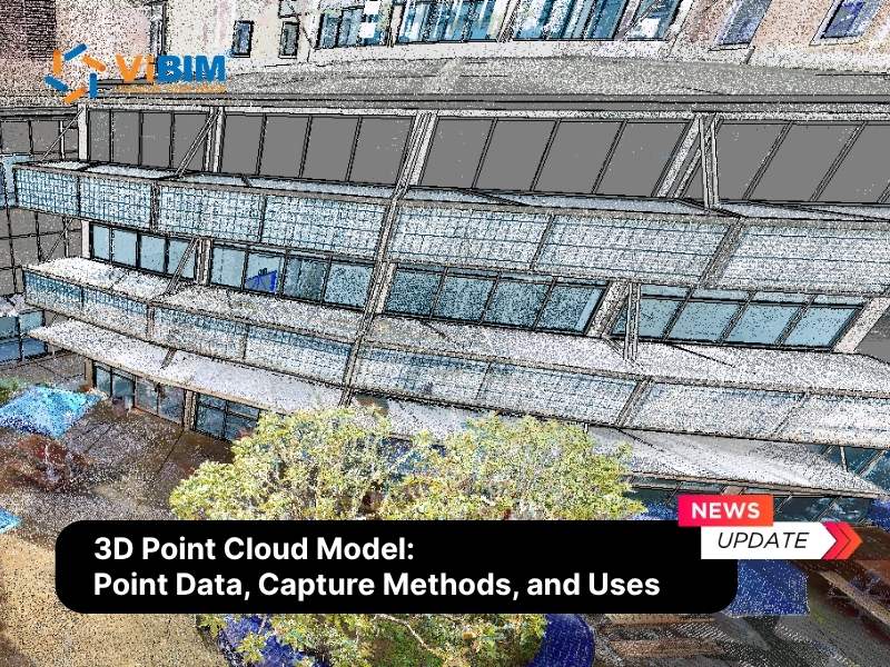
For an existing building, RCP, RCS, and E57 are common point-cloud inputs. Capturing and registering that survey data occurs earlier in the scan to BIM workflow; 3D BIM modeling begins once the source is ready to support object creation.
How Detailed Should a 3D BIM Model Be at Each Project Stage?
Use the lowest level of detail and information that fully supports your project’s next decision. Your intended use, project stage, required tolerance, and source-data quality determine that level; choosing a higher LOD without a defined use adds modeling work without improving the decision.
Level of Development and BIM dimension describe different things. LOD defines how reliably an element supports a stated use. A BIM dimension identifies associated information, such as time in 4D or cost in 5D. Both concept and construction-documentation models can remain 3D while carrying different levels of development.
The table maps common project stages to the amount of model information they normally need:
| Project stage | Detail that is enough | What that detail supports |
| Concept and feasibility | Massing, floor plates, approximate openings | Area schedules, planning discussions |
| Design development | Real element types, correct thicknesses, main services routed | Coordination between disciplines, early quantities |
| Construction documentation | Accurate element sizes, locations, interfaces, penetrations, and service clearances | Coordinated documents, tender quantities, issue detection |
| As-built record | What is actually there, verified against the survey | Handover, operations, later refurbishment |
Over-modeling creates objects, parameters, and coordination work that the current stage cannot use. Matching the model to the level of development required by its intended use keeps the scope measurable.
Existing-building models also depend on what the survey captured. A Leica BLK2GO point cloud has lower point density than a terrestrial laser scan, which can limit consistent LOD 300 coverage across all elements. Confirm the capture method and registration quality before modeling if your project requires high detail and accuracy.
What Files Come With a Delivered 3D BIM Model?
A complete delivery package normally includes the native authoring file, an agreed exchange file, model-generated drawings, and the object data required by the project scope. Define your exact package before modeling because each format preserves a different part of the model.
Each part preserves something different.
- The native file, usually .rvt. The authoring format retains Revit objects, parameters, relationships, and editing behavior.
- The open exchange file, .ifc. The project must specify IFC2x3, IFC4, or another required schema. Software implementations and model-view settings determine which geometry and properties transfer successfully.
- The drawings, .dwg or PDF. Plans, sections, and elevations cut from the model rather than drawn separately.
- The required object data. The agreed parameters belong on the model objects; a separate schedule or spreadsheet can be included as a checked export for review.
The delivery agreement should also name the transfer route and the person authorized to issue files. ViBIM uses controlled routes such as FTP, Box, Autodesk Construction Cloud, and Cintoo, with the project manager responsible for formal transfers.
Once the model objects are stable, a 4D BIM model can link them to construction schedules and sequence the build phase by phase before crews ever set foot on site, which turns every schedule review into a visual walkthrough instead of a spreadsheet debate. When those same objects later carry unit rates drawn from verified quantities, the result is a 5D BIM model that keeps estimates aligned with what was actually measured, which is why naming, classification, and complete parameters matter so much downstream. An accurate as-built model can also support a digital twin once operational data is connected. If you work for a survey or reality-capture firm, confirm that the formats suit both your review process and the final client’s software.
Five Checks to Run Before You Accept a 3D BIM Model
Before you accept the delivered model, check its geometry, parameters, survey deviation, scope completeness, and data consistency against the approved scope, LOD, tolerance, and naming rules.
Run the checks in this order:
- Geometry. Confirm that elements sit on the correct levels and coordinates, use the correct hosts, and contain no unintended duplicates.
- Parameters. Open the required schedules and verify that mandatory fields, such as type, classification, and fire rating, are populated in the agreed format.
- Deviation against the survey. Compare an existing-building model with its registered point cloud and confirm that measured differences remain within the agreed tolerance.
- Scope completeness. Check every required discipline and element category against the signed scope, including exclusions and inaccessible areas recorded as assumptions.
- Data consistency. Verify that naming conventions, classification codes, units, and parameter formats remain consistent across discipline models.
The signed project requirements remain the acceptance baseline. The ISO 19650 series provides a framework for managing and exchanging project information, while the BIMForum LOD Specification can help define the reliability expected from modeled elements. Neither replaces the project-specific scope and tolerance agreed by the parties.
What to Agree On Before 3D BIM Modeling Starts
Before 3D BIM modeling starts, you and the modeling provider need to agree what the model will support, what qualifies as an acceptable result, and how project information will be exchanged. These decisions define the work and give the acceptance review measurable criteria.
Your pre-modeling agreement needs to answer three questions:
- What does the model need to support? Define the intended uses, required disciplines, deliverables, and whether the geometry comes from design intent or measured existing conditions.
- What counts as acceptable? Record the LOD, required object information, tolerance, exclusions, naming rules, and treatment of areas the source data does not cover.
- How will you exchange information? Agree the native format, IFC schema, coordinate system, CDE or review platform, and authorized transfer route. When a client supplies point-cloud data, ViBIM recommends RCS files no larger than 5 GB each or one compressed dataset per transfer.
For survey-based projects, these scope decisions also drive price. LOD, the number of disciplines, capture quality, and building scale determine the production estimate; the scan to BIM cost guide explains how each factor affects the price.
What Software Is Used to Create a 3D BIM Model?
3D BIM modeling uses authoring software to create objects and coordination, point-cloud, and issue-management tools to check the result. The workflow determines which tools and exchange formats your project needs.
The table shows the role of each tool and how it relates to ViBIM’s workflow:
| Tool | Primary role | ViBIM workflow |
| Revit | BIM authoring | Primary authoring platform |
| Archicad | BIM authoring | IFC exchange in the client workflow |
| Tekla Structures | Structural authoring | IFC exchange in the client workflow |
| Navisworks Manage | Model federation and clash review | Coordination and QC |
| Autodesk Construction Cloud | CDE and model review | Controlled sharing and review |
| ReCap Pro | Point-cloud preparation | RCP and RCS processing |
| Cintoo Cloud | Point-cloud and model review | Cloud review |
| BIMcollab | Issue management | BCF issue tracking |
ViBIM authors in Revit BIM software. When a client workflow uses Archicad or Tekla, the team exchanges the model through the agreed IFC schema.
The IFC standard supports model-data exchange, but the chosen schema and software affect what transfers. Name the schema, receiving application, and early exchange test in your brief. The BIM software guide compares common authoring and review tools.
Can You Download a Ready-Made 3D BIM Model?
You can download ready-made BIM objects for individual products, but your project-specific building model must be created from design information or field-verified survey data. A component library cannot supply the geometry, relationships, and project data of a building that has not been modeled.
Platforms such as BIMobject and BIMsmith provide manufacturer objects for products including doors, fixtures, and equipment. Each object can contain its own geometry and parameters. The project model is created by placing, configuring, and coordinating those objects with the walls, floors, structure, services, and spaces of the actual building.
Review downloaded objects before use. Their parameter names, classification codes, units, geometry detail, and file size may not match your project standard. Map the required fields and test each object in a schedule before adding it to the production model.
Where a 3D BIM Model Falls Short
The model falls short when its source data, agreed scope, object information, or coordination process cannot support the intended use. It can organize available information, but it cannot recover geometry that was never captured or supply data the project never required.
Record five limitations before you use the model downstream:
- Source coverage. Scanners and drawings may leave inaccessible areas, occlusions, or outdated conditions unresolved.
- Scope and LOD. Elements outside the agreed disciplines or level of development will not be reliable for decisions that need more detail than you contracted for.
- Parameter completeness. A model can contain the correct geometry while required classifications, ratings, or asset fields remain incomplete.
- Coordination and version control. Discipline models can diverge when teams exchange files at different times or work from superseded versions.
- Software exchange. Geometry and properties may map differently between native authoring files and IFC implementations.
These limits carry into later BIM dimensions: missing geometry weakens 4D sequences, unreliable quantities weaken 5D estimates, and empty asset fields weaken 7D maintenance records.
Survey-based models expose the source limit. Scanners record only visible surfaces, leaving ceiling voids, service risers, and areas behind fixed equipment unmeasured. Ask for delivery notes that separate inferred geometry from verified conditions before you rely on either.

Why Choose ViBIM for 3D BIM Modeling
ViBIM is a fit for survey and AEC firms that need independently checked models and delivery capacity that can scale with a defined scope. Its 3D BIM modeling services tie acceptance checks and delivery windows to approved project requirements, so clients can verify both quality control and schedule before handover.
Outsourcing fits teams whose project demand arrives in batches or whose delivery deadline is shorter than the time required to recruit and train an internal BIM team. An in-house team remains more suitable for continuous workloads where the required software, coordination process, and QC standards are already established.
Every ViBIM project moves through three controlled stages:
- Scope review. The project manager confirms the inputs, disciplines, LOD, deliverables, exclusions, and estimated hours.
- Production. Modelers work to the approved project requirements and discipline standards.
- Independent review. Two independent QC layers check geometry, parameters, survey deviation, missing elements, and data consistency before handover.
The capacity behind that workflow is supported by four operating facts:
- More than 250,000 hours of Scan to BIM delivery
- A 99% on-time delivery rate
- 30+ staff, most working in production, project management, and QC
- Quotes returned within 12 to 24 hours, with a free trial available to new clients
After scope review, ViBIM converts the estimated modeling hours into a planned delivery window. Representative ranges show how production capacity is scheduled:
| Modeling hours | Typical business-day window |
| 10 to 100 | 1 to 4 days |
| 300 to 500 | 8 to 12 days |
| 1,500 to 2,000 | 22 to 29 days |
When registered survey data is the source, ViBIM applies the same scope and QC controls through the checked model package in its point cloud to BIM services.