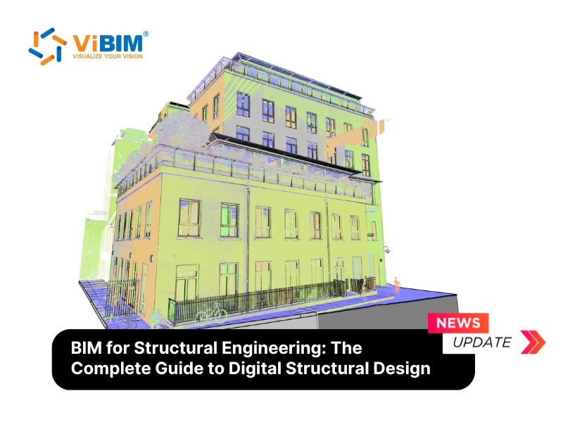
Building Information Modeling transforms how structural engineers design, analyze, and document load-bearing systems. BIM for structural engineering is a digital approach that creates intelligent 3D models containing geometric data, material specifications, and behavioral properties of every beam, column, foundation, and connection in a building’s framework.
Structural engineers now use BIM platforms to simulate gravity loads, wind forces, and seismic events before construction begins. This shift from 2D line drawings to parametric models reduces calculation errors by enabling direct integration with finite element analysis software. By adopting BIM, structural engineers unlock critical benefits, including enhanced design accuracy, automated clash detection with architectural and MEP systems, and significantly improved collaboration that reduces costly rework during construction.
In this guide, we will explore the essential aspects of digital structural design to help you navigate this industry shift. We will break down the core components of a structural BIM model, compare its advantages over traditional drafting, and review the top software tools currently driving the market. Finally, we will discuss practical implementation workflows and how leveraging specialized services from ViBIM can optimize your projects and ensure successful delivery.
What is BIM for Structural Engineering?
BIM for structural engineering is a model-based process where structural engineers create, analyze, and document building frameworks using intelligent 3D objects rather than 2D line work. The model contains parametric elements, which include columns, beams, slabs, walls, foundations, and connections that hold geometric dimensions, material grades, load capacities, and fabrication specifications.
Unlike general architectural BIM focused on spatial planning and aesthetics, structural BIM prioritizes load paths, member sizing, and connection details. The digital model connects to structural analysis programs through round-trip workflows. When an engineer changes a beam size in the model, the analysis software recalculates stress distributions and deflection values. These round-trip links transfer core structural data in both directions, though certain parameters — such as load combinations, meshing settings, and boundary conditions — may need manual verification after each exchange. This interoperability still represents a major advance over 2D workflows, where engineers re-entered all data from scratch.
Components of a Structural BIM Model
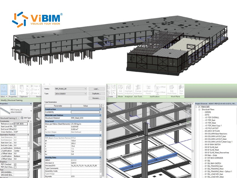
A robust structural BIM model is more than just geometry; it is a database of information. Key components include:
- Intelligent Structural Elements: Parametric objects (beams, trusses, slabs) that automatically adjust their geometry based on defined rules.
- Analytical Data: Information on loads, boundary conditions, and material properties required for structural analysis.
- Documentation Data: Tags, dimensions, and schedules that are dynamically linked to the 3D model, ensuring 2D drawings are always up-to-date.
- Fabrication Details: Connection details and reinforcement data (LOD 400) ready for shop drawing extraction and CNC machine input.
Structural BIM vs. Traditional 2D Drafting
The transition from traditional 2D drafting to Structural BIM represents a fundamental shift from drawing static lines to building intelligent data. While 2D drafting relies on disconnected geometry that requires manual updates across every individual sheet, Structural BIM utilizes parametric objects linked to a central database. Below is the key differents:
- Information Depth: Traditional 2D drawings describe size and shape but lack the “information” central to BIM. BIM models contain precise geometry and data needed for procurement, fabrication, and maintenance.
- Consistency: In 2D drafting, a change in a floor plan requires manual updates to sections and elevations, leading to errors. In BIM, a change to a parametric object is automatically reflected in all views, schedules, and analysis reports.
- Coordination: 2D processes rely on overlaying drawings to find conflicts. BIM enables automated clash detection, identifying “hard” and “soft” clashes between structural and MEP elements instantly.
Key Benefits of BIM for Structural Engineers
Structural engineers gain eight measurable advantages when they adopt BIM processes over traditional 2D methods:
1. Enhanced Design Accuracy Through Clash Detection
Structural BIM identifies conflicts between beams, columns, and MEP systems before construction begins. The model compares structural elements against architectural and mechanical components in real time, flagging intersections that would otherwise become costly field problems.
Rather than relying on manual 2D overlays, automated interference detection algorithms can pinpoint specific “hard clashes”—such as a steel beam intersecting with major HVAC ductwork—or “soft clashes” regarding equipment clearance zones. Resolving these conflicts within the digital environment ensures that the structural geometry is fully valid for manufacturing and erection, thereby significantly minimizing expensive on-site rework and Requests for Information (RFIs).
2. Improved Collaboration Across Disciplines
BIM strongly enables IPD-style collaboration, breaking down traditional silos between structural engineers, architects, and MEP contractors. By utilizing a cloud-based Common Data Environment (CDE), project teams share a “single source of truth” where the structural model is constantly federated with other discipline models.
This interoperability ensures that all stakeholders visualize the same design iteration simultaneously. Consequently, communication shifts from reactive email exchanges to proactive model coordination, effectively aligning the mental models of the entire project team and reducing the risk of misinterpretation during construction.
3. Faster Documentation and Drawing Production
BIM enables automatic generation of construction documents directly from the model, significantly reducing documentation time while improving consistency. The primary advantage lies in parametric change management: a modification to a column size or beam location in the 3D model instantly propagates to all associated sheets, schedules, and material takeoffs. This automation eliminates the tedious requirement to manually update multiple 2D drawings, thereby accelerating the delivery of construction documents while significantly improving consistency across the drawing set.
4. Seamless Integration with Structural Analysis Software
Modern BIM ecosystems facilitate a round-trip exchange of data between physical modeling tools (like Revit) and analytical software (such as Robot Structural Analysis or ETABS). Instead of maintaining two separate, disconnected models, the BIM environment houses both physical geometry and analytical properties—including loads, boundary conditions, and material strengths.
This interoperability allows structural analysis results to automatically update the analytical model within Revit. For instance, if an analysis determines that a steel member requires a larger section to withstand calculated loads, the updated section data synchronizes back to the analytical model — and from there, engineers update the physical model and documentation. This workflow significantly reduces the risk of data entry errors inherent in manual model recreation.
5. Accurate Quantity Takeoffs and Cost Estimation
BIM transforms the structural model into a high-fidelity database, enabling the extraction of reliable material quantities—such as steel tonnage, concrete volume, and rebar weight—when the model is built to an agreed LOD and modeled consistently. Unlike traditional manual takeoffs which are prone to calculation errors, BIM-generated schedules are dynamic; they update automatically as the model evolves.
This capability supports “5D BIM” (Cost), allowing quantity surveyors and estimators to generate accurate Bills of Quantities (BOQ) rapidly. The availability of reliable data assists project owners in budget forecasting and helps contractors order materials with greater precision, thereby minimizing site waste.
6. Better Constructability and Fabrication Support
Structural BIM bridges the gap between engineering design and physical construction by enabling a higher Level of Development (LOD). Models can be detailed to LOD 400, including exact connection details, bolt locations, and weld specifications suitable for fabrication.
This data-rich environment supports Design for Manufacture and Assembly (DfMA). Structural steel fabricators can export the BIM data directly to CNC machinery for automated cutting and drilling, while rebar detailers can generate bending schedules directly from the model. This digital-to-physical workflow accelerates the fabrication process and ensures that components fit perfectly upon arrival at the construction site.
7. Sustainability and Material Optimization
BIM provides the computational framework necessary to assess the environmental impact of structural decisions early in the design phase. By integrating Life Cycle Assessment (LCA) tools, engineers can calculate the embodied carbon of various structural systems—comparing timber, steel, and concrete options—to select the most sustainable solution.
Furthermore, topology optimization algorithms within BIM software can identify areas of structural inefficiency, suggesting material removal in low-stress zones. This optimization reduces the overall material volume required without compromising structural integrity, aligning project goals with modern sustainability standards and green building certifications.
8. Reduced Rework and Construction Errors
The cumulative effect of accurate modeling, clash detection, and better visualization is a substantial reduction in on-site errors. BIM allows for a “digital rehearsal” of the construction process (4D BIM), enabling teams to visualize the erection sequence and identify logistical bottlenecks before they occur.
Industry data indicates that BIM-driven projects significantly reduce the volume of Requests for Information (RFIs) and Change Orders related to design conflicts. By resolving issues virtually, the construction phase proceeds with fewer interruptions, protecting the project schedule and preventing the cost overruns associated with tearing down and rebuilding faulty work.
BIM Workflow for Structural Engineering Projects
A BIM workflow for structural engineering integrates 3D modeling, analysis, and detailing to streamline projects from concept to fabrication, enhancing collaboration and reducing errors. By maintaining a centralized data environment throughout these phases, engineering teams ensure that the design intent is preserved, coordination is seamless, and information remains consistent from the first sketch to the construction site.
Phase 1: Conceptual Design and Structural Scheme
During the conceptual phase, the BIM model serves as a simulation environment for rapid “optioneering.” Engineers generate simplified massing models to evaluate different structural framing systems—such as comparing a steel grid against a post-tensioned concrete slab—based on volumetric data and material costs. At this stage, parametric constraints are established to define preliminary load paths and grid geometry, enabling the team to visualize how the structural skeleton aligns with the architectural intent before detailed calculations begin.
Phase 2: Design Development and Analysis
This stage relies on the “round-trip” interoperability between the physical BIM model and analytical software. The analytical model—a subset of the BIM database containing nodes, loads, and boundary conditions—is exported for Finite Element Analysis (FEA). Once member sizing, deflection limits, and code compliance are verified in the analysis engine (e.g., Robot, ETABS), the optimized data is synchronized back into the central BIM model. This process automatically updates element properties, such as beam depths and reinforcement ratios, ensuring the design is structurally sound without manual remodeling.
Phase 3: Construction Documentation
The focus shifts to transforming the coordinated 3D model into legally binding construction deliverables. Plans, sections, and framing elevations are not drawn but are “live views” extracted directly from the central database. Intelligent tags and annotations pull data (such as material grades and member marks) directly from the model elements. Because these 2D views are associative, any modification to the 3D geometry instantly propagates across all drawing sheets and quantity schedules, guaranteeing that documentation always reflects the latest design iteration.
Phase 4: Fabrication and Construction Support
In the final engineering stages, the model advances to LOD 400, incorporating fabrication-ready details such as steel connection plates, bolts, and rebar bending shapes. Steel fabricators utilize this high-fidelity data to generate shop drawings and drive CNC machinery for automated cutting and drilling. Simultaneously, site teams use the structural model for 4D sequencing, planning the erection order of precast elements and managing crane logistics to ensure safe and efficient installation.
Top Software Tools for Structural BIM
A variety of platforms support structural BIM workflows, each with specific strengths:
- Autodesk Revit: The industry standard for multidisciplinary BIM, offering strong integration with analysis tools and documentation capabilities.
- Tekla Structures handles highly detailed steel and concrete models at fabrication level. Detailers generate shop drawings and drive CNC machinery directly from the model. It pairs with Tekla Structural Designer, a separate analysis and design tool that automates code-based member sizing for steel, concrete, and timber structures. Data flows between the two products, connecting the design model to the constructible model.
- Robot Structural Analysis Professional: Provides advanced analysis capabilities and bidirectional links with Revit.
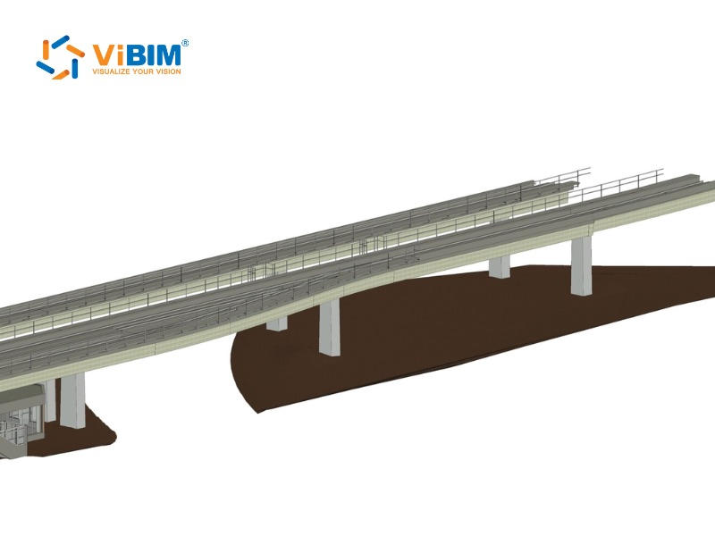
- OpenBuildings Designer (formerly Bentley AECOsim Building Designer): A robust platform often used in infrastructure and civil engineering projects, offering strong parametric modeling capabilities.
- Navisworks: Essential for clash detection and coordination reviews.
Selecting the right technology stack is critical for maximizing efficiency. For a comprehensive comparison of features, licensing, and suitability for various project types, please refer to our in-depth guide on the best BIM software currently available in the market.
How Do Structural Engineers Successfully Implement BIM?
Transitioning from traditional workflows to a fully integrated BIM environment requires a strategic overhaul of business processes, technology, and staff competencies. Successful implementation is rarely immediate; it follows a structured roadmap designed to minimize disruption while maximizing long-term ROI.
1. Establishing a Robust BIM Execution Plan (BEP)
Before modeling begins, firms must define the “rules of engagement” through a comprehensive BIM Execution Plan. This document serves as the project’s operational manual, outlining specific standards such as file naming conventions, coordinate systems, and the required Level of Development (LOD) for structural elements at each phase. Adopting international standards, such as ISO 19650, ensures that information management remains consistent and interoperable across different stakeholders.
2. Upgrading Hardware and Software Infrastructure
Structural BIM places significantly higher demands on computing power than 2D CAD. Implementation involves investing in high-performance workstations capable of handling complex parametric models and computationally intensive finite element analysis (FEA). Furthermore, establishing a Common Data Environment (CDE)—typically cloud-based—is essential to facilitate real-time model sharing and version control between the structural team and other disciplines.
3. Comprehensive Training and Change Management
The most significant barrier to adoption is often the “skill gap.” successful implementation prioritizes tiered training programs not just on software interface (e.g., Revit or Tekla), but on the collaborative workflow itself. Engineers must learn how to model for analysis, how to manage bidirectional data links, and how to interpret clash detection reports. Effective change management addresses the cultural shift, moving the team’s mindset from “drawing lines” to “managing information.”
4. Executing a Controlled Pilot Project
Rather than applying BIM to all active projects simultaneously, firms typically select a “pilot project” to validate new workflows. Ideally, this project should have a moderate level of complexity and a reasonable timeline. The pilot serves as a sandbox to test the interoperability between modeling and analysis tools, refine template settings, and identify potential bottlenecks. “Lessons learned” from this initial deployment are then documented to optimize the standard operating procedures for future projects.
Common Challenges in Structural BIM Adoption
While the long-term ROI of BIM is well-documented, the transition from traditional CAD to a digital workflow is resource-intensive. Structural engineering firms must be prepared to navigate a disruptive implementation phase characterized by four primary hurdles.
- High Initial Financial Investment: Adopting BIM requires a substantial upfront capital outlay that goes beyond purchasing software licenses. Firms must upgrade to high-performance workstations capable of processing complex 3D datasets and invest in server infrastructure for the Common Data Environment (CDE). For small to mid-sized engineering practices, this “software plus hardware” cost burden can significantly impact cash flow before any project efficiency is realized.
- Steep Learning Curve and Productivity Dips: The shift from 2D drafting to parametric modeling involves a steep learning curve. During the initial training period, engineering teams often experience a temporary drop in productivity as they master complex tools like Revit or Tekla Structures. Furthermore, the industry currently faces a shortage of “BIM-ready” structural engineers, making recruitment and retention of skilled talent a persistent operational challenge.
- Interoperability and Data Loss Risks: Despite advancements in open standards like IFC, seamless data exchange remains a technical challenge. “Round-tripping” models between physical authoring tools and structural analysis software can sometimes result in data loss or geometry corruption. Engineers often spend valuable time manually verifying that loads, boundary conditions, and material properties have transferred correctly, mitigating the risk of analysis errors.
- Cultural Resistance to Collaborative Workflows: Successful BIM adoption is as much about people as it is about technology. Transitioning from isolated, linear workflows to a collaborative, real-time environment requires a fundamental mindset shift. Senior engineers accustomed to traditional 2D processes may resist these changes, viewing the transparency and strict data requirements of BIM as an impediment rather than an enabler of design quality.
Outsourcing 3D BIM Modeling Services at ViBIM for Structural Engineers
Navigating the complexities of digital transformation can be resource-intensive. ViBIM serves as your strategic partner, offering specialized outsourcing solutions that extend your team’s capabilities without the overhead of expanding in-house staff.
With over 11 years of experience and 1,000+ successful projects globally, ViBIM is not just a drafting service but a technical partner proficient in Scan to BIM and advanced modeling. Our structural engineering support focuses on:
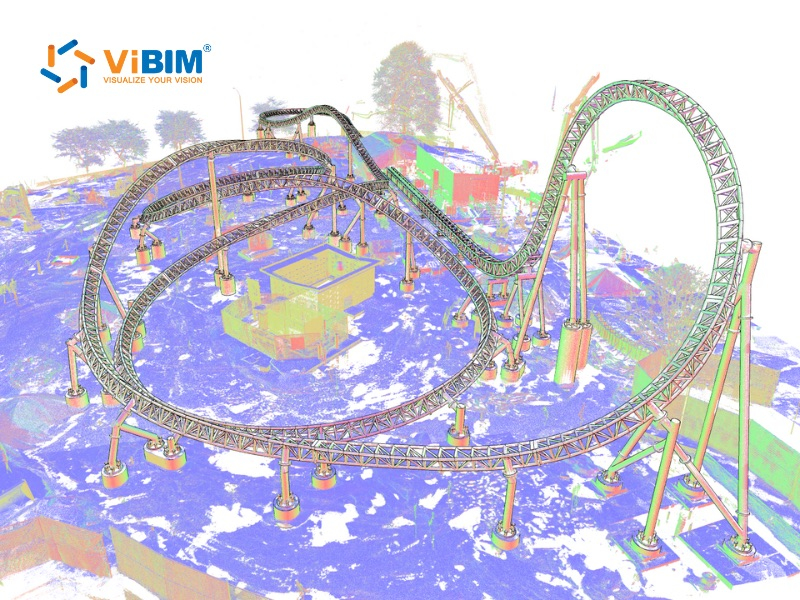
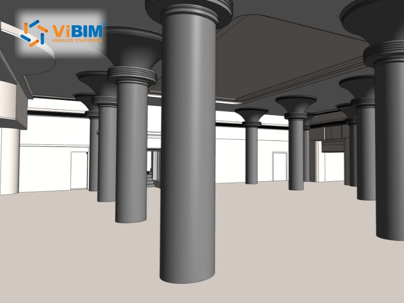
- Structural Scan to BIM: We convert raw point cloud data into precise, intelligent 3D Revit models. This Scan to BIM service is critical for renovation and retrofit projects, ensuring that existing structural conditions—beams, columns, and trusses—are captured with millimeter accuracy for reliable assessment.
- Custom Revit Family Creation: Through our expert Revit Family Creation services, we build parametric structural families (LOD 200–500) tailored to your specific project needs, ensuring data consistency and ease of use across your models.
- 3D Modeling & Coordination: From schematic design to detailed construction documentation, our team ensures your models adhere to rigorous international standards. We handle the heavy lifting of model cleanup, clash detection, and documentation, allowing your senior engineers to focus on analysis and design optimization.
Contact ViBIM for precision Structural Scan to BIM services to optimize your next project.

FAQs
Is BIM mandatory for structural engineers?
BIM is not universally mandatory yet, but it is increasingly required for government and public sector projects in many countries, including the UK (BIM Level 2 mandate) and parts of the US. Private clients are also demanding BIM deliverables to ensure better asset management.
Can BIM be used for existing building structural assessments?
Yes, utilizing Scan to BIM technology allows you to create accurate structural models of existing buildings from laser scan data. This is invaluable for retrofit projects, structural integrity assessments, renovation planning, and establishing reliable data for Scan to BIM for FM workflows.