Clash detection in Navisworks plays a key role in coordinating BIM projects by identifying design conflicts before construction begins. The Clash Detective tool in Navisworks helps you review the entire project model and detect interferences across disciplines, including architecture, structure, and MEP systems. By identifying these clashes early, we can reduce design errors and prevent costly rework later in the project.
Autodesk Navisworks, a 3D design review solution from Autodesk, provides a comprehensive environment for project coordination. Its standout capability is real-time clash detection, which helps teams identify design collisions instantly and make adjustments to prevent rework and budget overruns during construction.
Using Navisworks for clash detection offers five key benefits: it enhances coordination across multiple platforms, supports immersive 3D visualization for real-time resolution, ensures accurate collision detection, minimizes design errors with the Clash Detective tool, and enables time-based clash detection for 4D BIM projects. The workflow involves model preparation, creating and configuring clash tests, running and reviewing results, resolving clashes, and generating customized reports for documentation.
This article will guide you through everything from understanding Navisworks and its clash detection process to exploring its benefits, challenges, and best practices. Keep reading to discover how to optimize coordination and accuracy in your next BIM project.

Navisworks overview
Autodesk Navisworks is a 3D project review software that allows us to combine multiple design models into one shared environment for coordination. The Navisworks software functions as a model aggregator, gathering 3D models and their associated data from platforms like Revit and AutoCAD into a single, integrated workspace. This capability makes it easier for us to review the project from different disciplines and identify inconsistencies early in the design phase.
Navisworks is widely used across the construction industry because it supports a wide range of BIM and plant design applications. The strongest feature is its clash detection function in Navisworks Manage, which detects collisions among architectural, structural, and MEP systems in real time. By using these interference management tools, we can anticipate issues, correct them before construction, and reduce unnecessary delays and rework.
What is clash detection in Navisworks?
Clash detection in Navisworks means the act of using the Clash Detective tool to help detect interferences among different building systems within a 3D model. The tool identifies, inspects, and reports conflicts between elements from multiple disciplines early in the design process, reducing the chance of human error during model reviews. This feature is available in Autodesk Navisworks Manage and supports both geometry-based and point cloud clash tests.
Clash detection can be used either as a final quality check after design completion or as a continuous monitoring process throughout the project. By integrating this function into the coordination workflow, we can maintain model accuracy, improve collaboration between design teams, and avoid rework during construction.
Top 5 benefits of using Navisworks for BIM clash detection
There are five key benefits that make Navisworks an effective platform for managing BIM coordination and clash detection across complex projects.
- Enhanced coordination across multiple platforms: Navisworks combines design models from different disciplines into a single federated environment, supporting more than 60 file formats, including Revit, AutoCAD, and ReCap. This wide compatibility allows project teams to compare, detect, and resolve interferences early. With shared reports and integrated collaboration, coordination becomes smoother, reducing rework and communication gaps among disciplines.
- Immersive 3D visualization for real-time resolution: The platform provides interactive visualization tools that allow teams to navigate models freely and identify conflicts in real time. The photorealistic rendering and walkthrough capabilities provide a clear view of how different systems interact, helping stakeholders make quick, confident design decisions. This process reduces design errors and supports better project outcomes.
- Accurate and efficient collision detection: The advanced clash detection system in Navisworks supports filtered clash tests that can be saved and reused for consistent checking. This precision helps maintain coordination quality across multiple project stages. By identifying potential issues quickly and minimizing overlooked details, teams can maintain design accuracy and shorten review cycles.
- Reduced design errors with clash detective tool: The Clash Detective tool compares 3D geometry and laser-scanned point clouds to identify physical conflicts with high precision. Teams can address detected clashes directly within modeling software such as Revit or Tekla Structures, improving workflow efficiency. This accuracy reduces the risk of design inconsistencies that could lead to costly construction issues later.
- Time-based clash detection for 4D BIM projects: Integrating Clash Detective with the TimeLiner feature enables time-based clash analysis that predicts conflicts across construction stages. Automated detection across the schedule helps visualize when and where clashes might occur. By proactively rescheduling tasks, we can minimize on-site conflicts and maintain smooth project execution.
How to run clash detection in Navisworks?
The clash detection process includes five main steps that help maintain coordination across all models and disciplines.
- Step 1: Preparation and Model Setup
- Step 2: Creating Clash Tests
- Step 3: Configuring Clash Tests
- Step 4: Running and Reviewing Clash Tests
- Step 5: Resolving Clashes
In the next part, we will explore each step in detail to understand how the process works.
Step 1: Preparation and model setup
The preparation stage begins with importing all models into Navisworks to create a unified environment for coordination. This setup phase must strictly follow the established BIM implementation plan to ensure all stakeholders are using compatible versions and settings.
- Open Navisworks Manage.
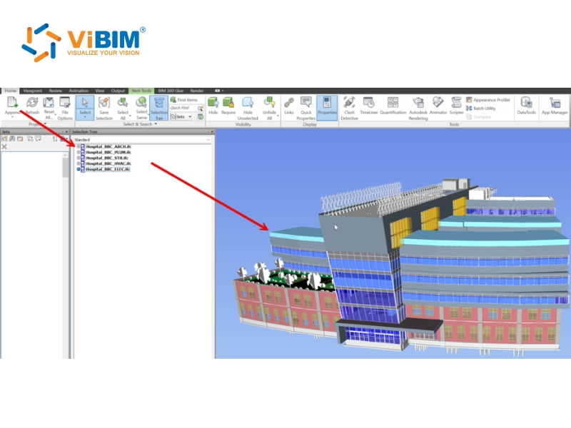
- Go to the Home tab → select Append (not Merge).
- Import each disciplinary model, including specialized BIM for MEP files and architectural sets.
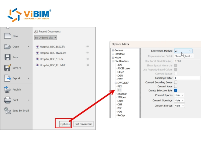
- Check and adjust import settings for IFC files.
- Verify all models use the same coordinate system for proper alignment.
Model alignment is essential for accurately detecting clashes. We use the Measure and Viewpoint tools to confirm that each model fits correctly in 3D space, and we resolve any alignment issues before proceeding to clash detection.
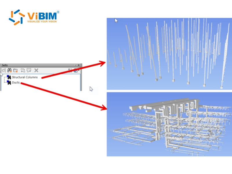
Organized models help manage tests more efficiently, so we create Search Sets to group elements by discipline, type, or area. Logical grouping, such as Structural Columns versus HVAC Ducts, supports better filtering and visualization during the review process.
A complete setup always finishes with saving and reviewing. We save the Navisworks file (.nwf), check all search sets for clear naming, and confirm that all models are visible and ready before starting the clash tests.
Step 2: Creating clash tests
A new clash detection process begins with creating clash tests in Navisworks, where models from different disciplines are compared under defined conditions:
- Open the Navisworks project.
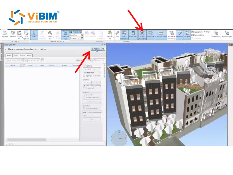
- Navigate to the Home tab > Tools panel > click Clash Detective. (Note: This feature is available only in Autodesk Navisworks Manage.)
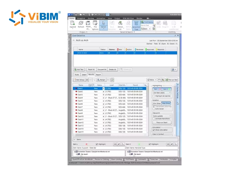
- Click the Add Test button at the top of the Clash Detective window to create a new test. The Select tab will automatically open to define the test criteria.
Step 3: Configuring clash tests
Configuring clash tests involves setting rules, selecting the objects to be tested, and defining how clashes are measured. This step ensures that the clash analysis runs efficiently and reduces irrelevant results.
Step 3.1: Set up clash rules
Setting clash rules is vital for streamlining the clash review process, as rules reduce the number of clash results by ignoring certain combinations of clashing items (false positives).
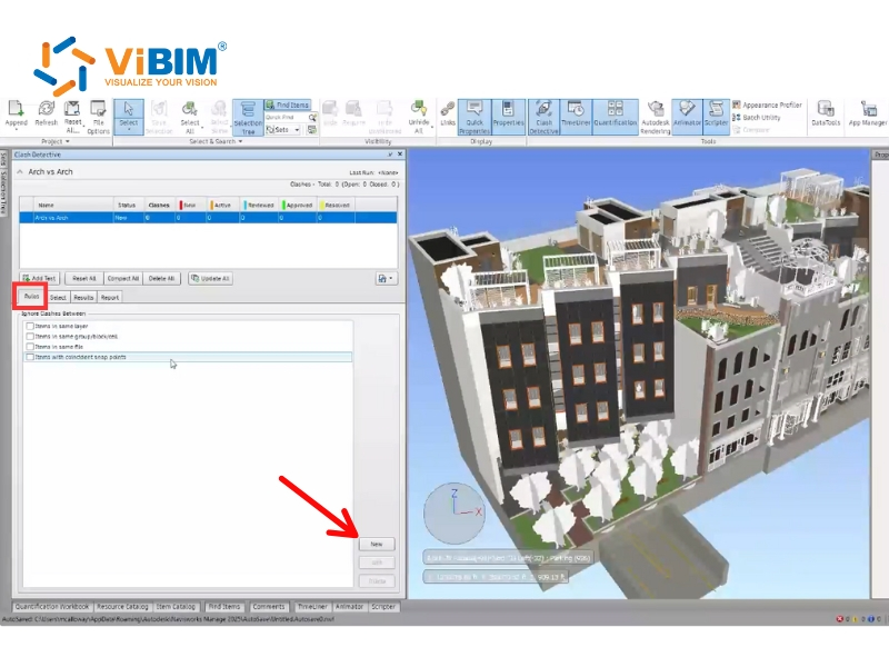
- Access the Rules tab.
- Select built-in Default Clash Rules to apply, such as Items in Same File (useful if testing only between separate files) or Items in Same Group/Block/Cell.
If we don’t want to use the built-in rules, we can customize one. To create a custom rule:
- Click New to start.
- Choose a template like Specified Selection Sets.
- Define required values in the Rule Description box, such as Category or Property.
- Select whether to search for that property on the Any Parent object.
Step 3.2: Select items for clash test (Selection A and B)
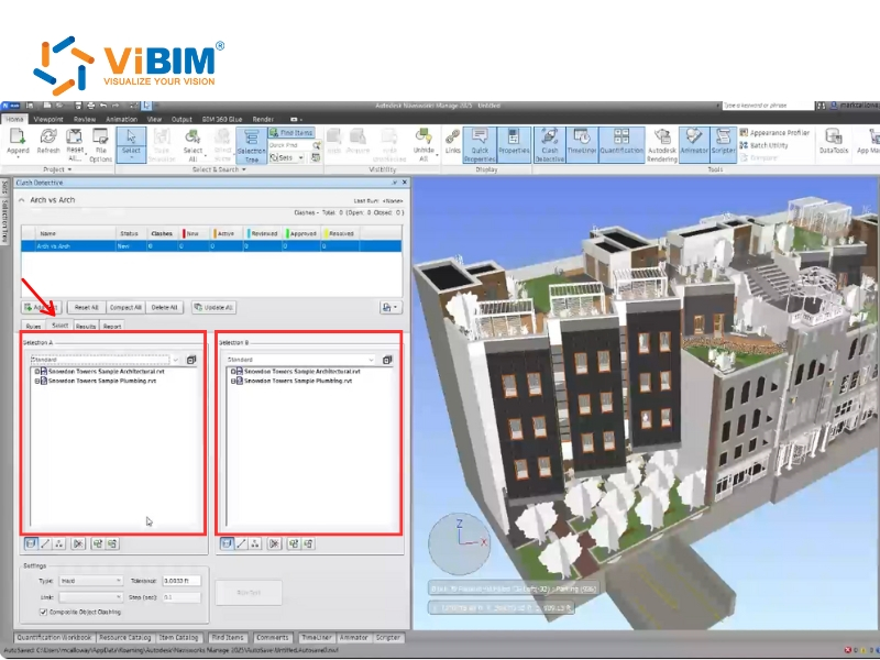
The Select Tab contains two identical panes, Selection A and Selection B, where we define the two sets of items to be compared, enabling efficient analysis and control. We select items using the drop-down lists or predefined Sets, which simplifies repeated setups.
Selection Sets act as static groups for the current project, while Search Sets are dynamic and reusable. During the early stages, we prioritize larger elements using the Clash the BIG Stuff First method and, optionally, activate the Self Intersect button to detect internal clashes within a set.
Step 3.3: Define clash type and tolerance
The test type defines how interferences are measured, and tolerance specifies the acceptable distance or overlap between elements.
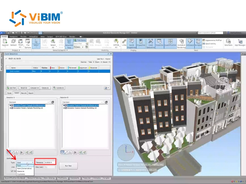
- Choose the test Type:
- Hard: Detects actual geometry intersections.
- Clearance: Checks for geometry within a specific distance (Tolerance) of other objects, commonly used for elements needing spacing like insulated pipes. Note that Clearance clashes differ from “soft” clashes, which rely on Object Animation.
- Duplicates: Identifies repeated or overlapping elements in the model.
- Enter the required Tolerance value. It is recommended to reduce tolerance values gradually during review to refine results.
- (Optional) Use the Link box to connect with other Navisworks tools such as TimeLiner for time-based clash checking.
Step 4: Running and reviewing clash tests
Running and reviewing clash tests executes the analysis and allows us to inspect the results systematically. This step is where the setup begins to yield actionable information.
Step 4.1: Run the Clash Test
After defining the selections, type, and tolerance, the test can be executed to identify potential interferences between model elements. Click the Run Test button to start the analysis; a progress bar appears to show its progress. If the process is stopped midway, the clashes found so far are still reported, and the test is saved with a Partial status. When the test finishes, the Results tab opens automatically, displaying all detected interferences for review.
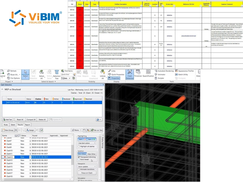
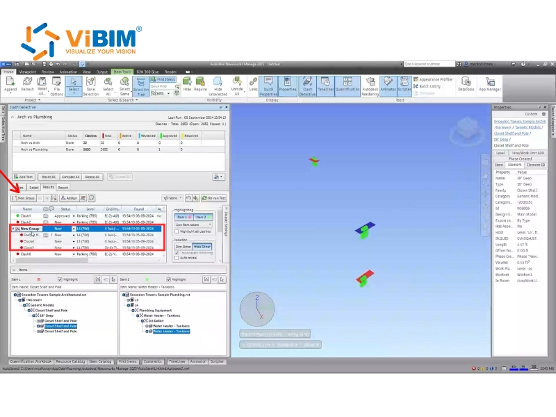
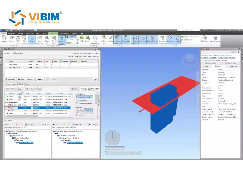
Step 4.2: Review and Group Clash Results
The results table lists every detected clash and allows sorting by parameters such as name, number, or workflow status, making it easier to manage large sets of results. Each clash can be selected to highlight the involved objects in the Scene View, automatically zooming in on the point of interference.
When several clashes relate to a single issue, we manually group them to maintain order and clarity, and grouped clashes appear as a single record in reports. Each group is named clearly and consistently, using a concise format such as Pipe_Steel Beam to improve traceability during coordination.
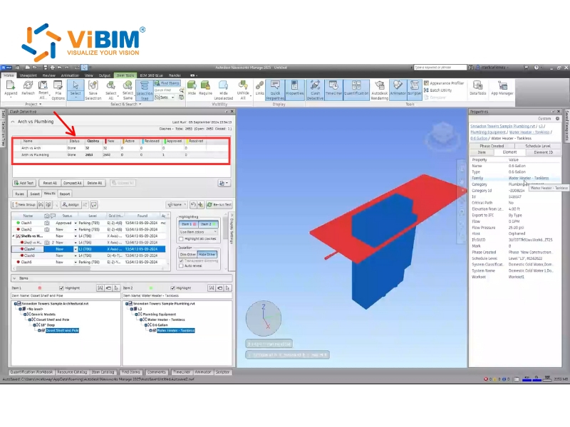
Step 5: Resolving clashes
At this stage, the focus shifts from detection to resolution, where we verify, categorize, and address each conflict identified in the clash test. We sort the results by the Status column, which follows a logical order from New to Active, Reviewed, Approved, and finally Resolved. Once a clash reaches the resolved stage, its status is displayed in yellow, signaling that the issue has been addressed within the model.
To fix a clash efficiently, we select the clashing item and click the SwitchBack button. SwitchBack sends the current view and selected object back to the source CAD software, such as Revit. Revit then automatically loads the associated project, locates the selected element, and zooms in for quick design adjustment. If SwitchBack fails to connect, selecting a higher node in the Selection Tree within Navisworks usually resolves the issue.
Before exporting the report, this video provides a clear visual demonstration of the clash detection and resolution process:
How to generate and customize the clash detection report?
We always complete the clash detection process by generating and customizing a detailed report. This report communicates all coordination issues to the design and construction teams who may not have direct access to Navisworks.
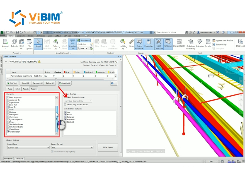
Step 1: Selecting Report Contents and Clash Group Display
In the Contents area, we select the check boxes for the data we want to display for each clash result:
- Quick Properties: Includes item-specific data for each clash based on defined properties.
- Selection Tree: Includes the complete path from the model root to the clash geometry.
- Images: Includes automatically captured screenshots of each clash for visual reference.
- Simulation Information: Includes scheduling and animation data if the model is linked to TimeLiner or Object Animation.
- Clash Group: Identifies which group an individual clash belongs to when exporting individual or grouped results.
- Group Headers Only: Displays summaries of clash groups and standalone individual clashes.
- Individual Clashes Only: Displays all individual clashes but does not separate them by group unless the Clash Group checkbox is selected.
- Everything: Displays both clash group summaries and all individual results contained within each group.
Step 2: Choosing Report Type and Format
Next, we determine how the results are organized across multiple tests by choosing the report type:
- Current Test: Generates a report for only the currently selected test.
- All Tests (Combined): Combines all test results into a single comprehensive file.
- All Tests (Separate): Creates individual report files for each clash test.
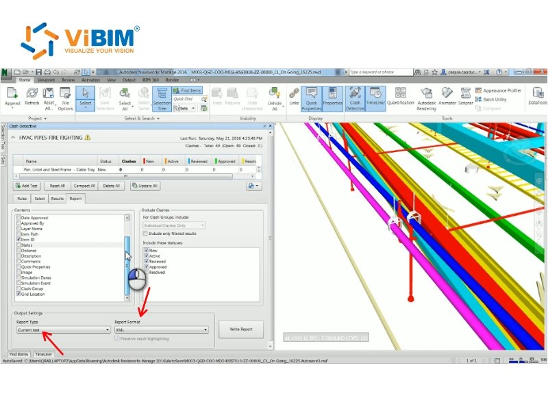
We then select the preferred report format to control the structure and usability of the exported file. The table below summarizes the five available formats, their output description, and key advantages:
| Format | Output Description | Key Benefit / Note |
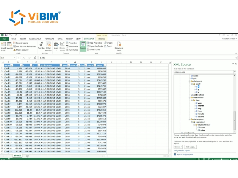
| XML | Creates an XML file containing all clashes and a JPEG of their viewpoints. | Allows users to export or import clash test data. |
| HTML | Creates an HTML file containing clash details and a JPEG of their viewpoints. | Generally used for detailed illustration. |
| HTML (Tabular) | Creates an HTML table with clash details and viewpoints. | Can be opened and edited in Microsoft Excel 2007 onwards. |
| Text | Creates a TXT file with clash details and links to JPEG images. | Requires a folder for storing related files. |
| As Viewpoints | Creates a folder in Saved Viewpoints with each clash saved as a viewpoint. | Includes comments with clash details for easy review. |
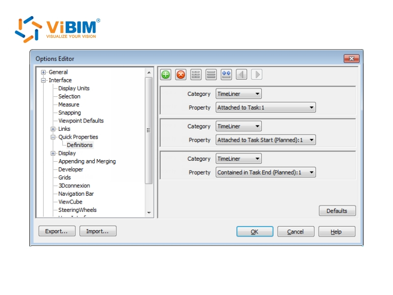
Step 3: Configuring Quick Properties for Time-Based Details
For time-based clash tests linked to TimeLiner, we include additional information about static packages via Quick Properties definitions.
- Click the application button and select Options.
- In the Options Editor, open Interface > Quick Properties > Definitions.
- Choose TimeLiner from the Category list.
- Select the property “Attach to Task: 1” in the Property box.
- Click OK to confirm. The next report will automatically include this added data when Quick Properties is enabled in the Report tab.
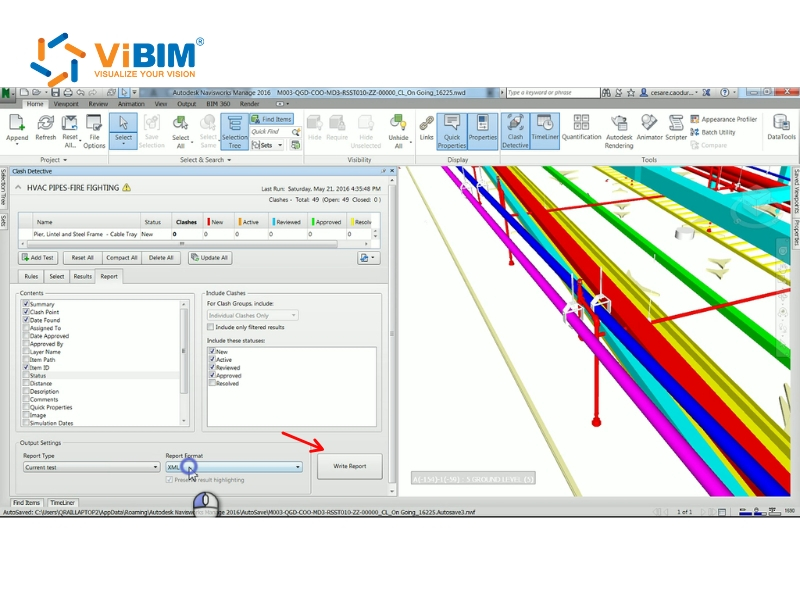
Step 4: Report Generation and Output
This is the final step in the report generation. Here, you click the Write Report button in the Report tab to generate your clash report. Choose your preferred output format such as XML, HTML, HTML (Tabular), or Text, and specify the destination folder along with a report name.
Step 5: Customizing HTML Appearance and Management
We can modify the visual style and structure of HTML or HTML (Tabular) reports by editing the XSL files named clash_report_html.xsl or clash_report_html_tabular.xsl. The default files are stored in the stylesheets folder within the Navisworks installation directory. To apply the customized layout, the edited versions must be copied into the same folder in any Navisworks search directory.
After all clashes have been addressed, we can click ‘Compact All’ to permanently remove results marked as ‘Resolved’ from the test. This action helps reduce file size and keeps only active and relevant issues in the project, making future coordination sessions more efficient and easier to manage.
You can review this detailed video that visually demonstrates the report generation and customization process here:
https://screencast.autodesk.com/Embed/Timeline/9cfe3fad-3432-4d07-9110-c4a14a7af2c4
What are the challenges and opportunities of Navisworks clash detection?
There are six key challenges that teams often face during Navisworks clash detection:
- Unmodeled openings for services: Missing openings for pipes, ducts, or conduits passing through slabs and walls are a recurring issue. Smaller penetrations of less than 3 inches are often excluded from modeling, but they can still affect material quantities and structural performance. Clash detection highlights these gaps early, allowing us to coordinate and define accurate openings before construction begins.
- Misaligned or partially embedded elements: Building elements, such as pipes or conduits, may appear partially buried within walls or floors due to incorrect elevation or placement. Navisworks helps identify these alignment issues through grouped clash views, so teams can adjust positions quickly and maintain consistent model accuracy across all disciplines.
- Safety route validation in 3D: Fire and Life Safety plans may differ from the coordinated 3D model, potentially causing egress or code compliance issues. Performing 3D egress path checks in Navisworks allows us to confirm that escape routes are accurately modeled and compliant, making safety validation visual and automated rather than relying solely on manual review.
- Incomplete or non-fabrication-level models: Many clashes occur because models are not developed with fabrication-level detail, especially in design-bid-build projects. This reduces the precision of clash detection but encourages the project team to define clear tolerances and collaborate early with fabricators. Doing so improves constructability and aligns model specifications with actual field conditions.
- Difficulties in managing and resolving issues: Identifying clashes is straightforward, yet tracking and resolving them across multiple trades remains challenging. Without structured workflows, issues can remain open or unresolved. Integrating Navisworks with coordination tools such as BIM 360 or Revizto enables us to assign tasks, follow progress, and verify that every clash receives a practical solution.
- Model data changes during file conversion: When transferring models between Revit and Navisworks, geometry, scaling, or element IDs may unexpectedly change, leading to inaccurate clash results. Establishing standard export procedures and conducting regular quality checks can reduce these inconsistencies and maintain data reliability throughout the coordination process.
While these technical hurdles are common, they often stem from broader strategic errors; identifying and avoiding these root causes is easier with our guide to common mistakes in BIM implementation.
Best practices for clash detection in Navisworks
Here are six practical tips that focus on specific tools and methods to enhance our efficiency in managing design conflicts and maintaining smooth and organized BIM coordination.
Tip 1: Review models visually before running clash detection
A good starting point is to visually review the model to spot obvious design conflicts before using Navisworks. This manual check helps remove unnecessary clashes, allowing the following automated process to focus only on genuine coordination issues.
Clean models always lead to cleaner results. If the model is not controlled beforehand, Navisworks can generate thousands of clash errors that are impossible to group or report efficiently, resulting in wasted time and effort during coordination.
Tip 2: Focus on major conflicts before fine-tuning
We always begin clash testing with large, critical building components, such as shafts, cores, tunnels, or structural elements that affect multiple systems. Using wider tolerances at first allows us to detect and address significant design conflicts that might require redesign rather than small model adjustments. Gradually narrowing the tolerances after resolving the main issues helps us capture minor interferences and refine the coordination model efficiently.
Tip 3: Customize clash reports with company branding
We prefer customizing clash reports to reflect our company’s identity, especially when sharing results with clients or project teams. By editing the default HTML report and replacing the Navisworks logo with our own, we maintain a consistent and professional brand presentation across deliverables.
We follow these 3 steps to insert our company logo and adjust the report settings for clearer visuals:
- Adjust hidden report export settings to improve image resolution and select file types such as PNG or JPG.
- Click the Application Button (Green N) → hold Shift → Options → Registry → Clash Detection → Reports.
- Modify Image Export size and Plugin type for sharper visuals.
Tip 4: Speed up fixes with Revit SwitchBack integration
We use the SwitchBack tool to link Navisworks directly to Revit, enabling us to quickly find and edit clash elements within their original design environment. This function simplifies the correction process by skipping manual searches and jumping straight to the exact location in Revit where the clash occurs.
The integration works through a simple sequence that connects both platforms seamlessly during coordination:
- In Revit → go to Add-Ins tab > External Tools > Navisworks SwitchBack.
- In Navisworks → open Clash Detective > Results > SwitchBack button.
- If files have moved, Navisworks prompts us to relink the RVT file.
Tip 5: Visualize clashes in Revit with Dynamo or Plugins
We often visualize clash points directly in Revit when team members do not have access to Navisworks Manage. Using Dynamo scripts or the BIM One Clash Sphere Generator plugin, we can display clash locations visually in the model to simplify review and coordination.
This workflow is straightforward and can be carried out in Revit by following 3 main steps:
- Export clash results as XML.
- Generate spheres in Revit showing clash locations by ID.
- Review clashes directly in Revit through schedules or linked models.
Tip 6: Coordinate in the Cloud with Autodesk Construction Cloud
We combine Navisworks Manage with Autodesk Construction Cloud to improve real-time model coordination and communication across teams. Glue handles live collaboration and notifications, while Navisworks Manage supports advanced clash detection, 4D/5D simulations, and quantity takeoffs.
We maintain effective cloud-based coordination by following the following sequence:
- Save clash groups as Viewpoints → Sync to BIM 360 Glue via Share Views.
- Rename and organize shared views for better traceability.
Frequently asked questions about Navisworks clash detection
Clash Detection: Revit vs. Navisworks?
Revit’s clash detection is limited to identifying conflicts within a single model, while Navisworks federates multiple file formats such as NWC, IFC, and DWG to detect inter-disciplinary clashes. Revit should be used for basic, single-discipline checks, such as MEP clashes within a single model, whereas Navisworks is best for coordination between MEP, architectural, and structural models or for checking against point cloud data.
Can Navisworks Simulate run clash detection?
Navisworks Simulate cannot run clash detection, as this feature is only available in Navisworks Manage. The key difference is that Navisworks Manage includes the Clash Detective tool, which enables users to efficiently identify, analyze, and report model interferences across multiple disciplines.
The article has outlined how Navisworks clash detection supports efficient BIM coordination through every stage of the workflow. It began with an overview of Navisworks and the concept of clash detection, followed by the top benefits of using the software for coordination. The guide then explained each step of running clash detection, from model setup to resolving conflicts, and described how to generate and customize reports. We also discussed challenges, opportunities, and best practices to help teams achieve accurate, consistent project outcomes.
ViBIM focuses on providing BIM Modeling services from Point Cloud data (Scan to BIM), using Revit as the primary authoring tool within the Autodesk platform. We implement these solutions for building surveys, existing and as-built documentation, and for design and engineering projects. Contact ViBIM today to discuss your specific project requirements and receive a complimentary quote for the best Revit BIM modeling services.
Vietnam BIM Consultancy and Technology Application Company Limited (ViBIM)
- Address: 10th floor, CIT Building, No 6, Alley 15, Duy Tan street, Cau Giay ward, Hanoi, Vietnam
- Phone: +84 944 798 298
- Email: info@vibim.com.vn