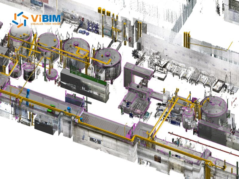
Building Information Modeling for MEP systems involves the creation of detailed, intelligent 3D models. These models represent a building’s complete mechanical, electrical, and plumbing infrastructure.
Key systems in the BIM for MEP include mechanical components such as HVAC, electrical networks for power and lighting, and plumbing systems for water supply and waste drainage. Architects can apply this modeling approach across all design stages, from the initial concept to the final construction documents.
MEP engineers constantly face pressure to design systems that strike a balance between performance, cost, and constructability. So, BIM provides a method for more effective design and sustainability, helping design teams improve their project delivery.
A structured coordination process typically begins with the use of the correct MEP BIM template and validation of the architectural model. Teams then develop the MEP model by discipline, perform clash detection, and work to review and resolve any conflicts.
This article from ViBIM introduces the benefits of BIM for MEP design and coordination, the systems included, the challenges faced, and the process for effective MEP modeling. The following sections will provide detailed explanations of each aspect to help readers understand how BIM influences modern building engineering.

What is BIM for MEP?
BIM for MEP refers to the use of Building Information Modeling (BIM) for designing, analyzing, and managing a building’s Mechanical, Electrical, and Plumbing (MEP) systems. The process connects design data with spatial information, enabling engineers to plan, analyze, and modify systems with greater accuracy. It supports collaboration between disciplines, helping teams design, coordinate, and manage complex MEP networks throughout the entire project lifecycle, laying the groundwork for Scan to BIM for FM.
A well-designed MEP system is essential to a building’s overall performance because it provides heating, ventilation, lighting, power, and water supply. By applying BIM techniques, teams can enhance system accuracy, detect conflicts early, and improve coordination between disciplines. This results in fewer errors, reduced rework, and greater overall project efficiency.
Key MEP systems in BIM coordination
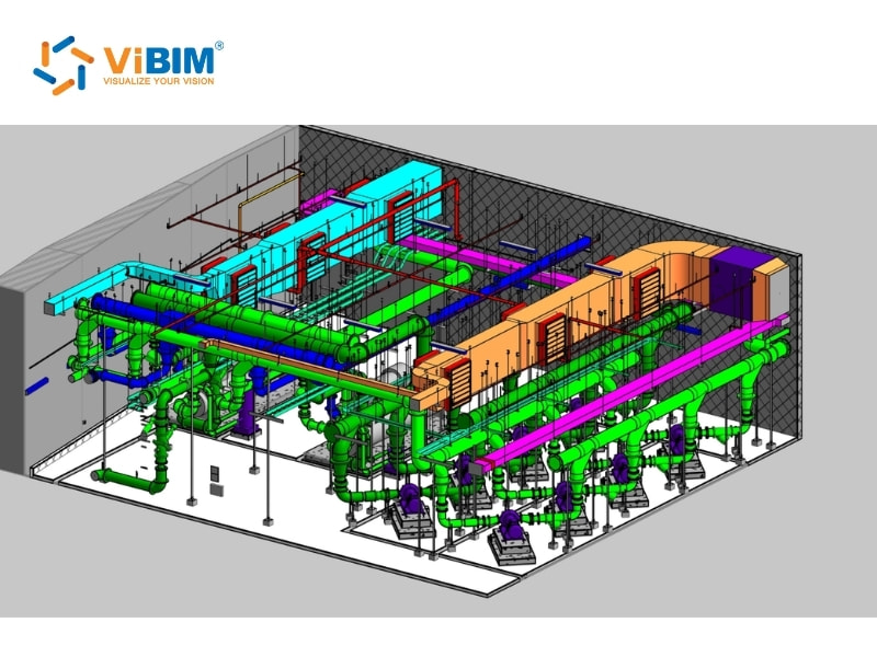
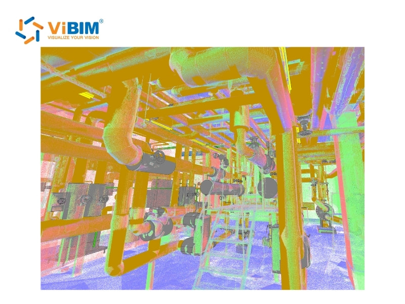
MEP systems continuously interact throughout a building, competing for the same physical spaces and requiring specific clearances to operate properly. These networks form a dense web of mechanical, electrical, and plumbing components that must fit and function together without conflict.
BIM creates a virtual environment that allows designers and engineers to study and optimize these interactions before construction begins. Each system brings its own modeling considerations and coordination priorities that must be addressed to ensure accurate integration into the overall building model.
MEP systems are complex and interdependent. BIM helps coordinate them effectively, and they are typically divided into three main disciplines: mechanical, electrical, and plumbing.
To understand the overarching workflow that prevents these complex system conflicts before they reach the construction site, read our essential guide on what is BIM coordination.
Mechanical Systems (HVAC and Related Components)
Mechanical systems control air quality, temperature, and comfort within buildings. They include HVAC ductwork, air-handling units, chillers, and heating or cooling pipes that occupy a significant amount of physical space.
BIM enables mechanical engineers to optimize ductwork layouts for improved airflow and energy efficiency, while performing thermal analysis to enhance insulation and indoor climate control. Equipment placement can also be refined in the model to reduce spatial conflicts and enhance overall system performance.
Electrical Systems (Power, Lighting, and Automation)
Electrical systems distribute power, support lighting, and connect critical services such as telecommunications, security, and building automation. These networks present unique coordination challenges due to their wide distribution and the requirement for specific safety clearances.
BIM helps designers visualize conduit paths, maintain safe distances from water-carrying pipes, and preserve working clearances around electrical panels. It also supports precise load calculations to prevent circuit overloading, energy-efficient lighting layouts for sustainability, and optimized cable routing to minimize installation errors.
Plumbing Systems (Water Supply and Drainage)
Plumbing systems manage water supply, waste removal, and fire protection within a building. They must balance gravity-dependent flow requirements with efficient use of space and accessibility for maintenance.
BIM enables engineers to verify pipe slopes, diameters, and routing, thereby preventing clashes with other systems. It also supports water conservation planning through optimized layouts and facilitates the integration of fire protection systems, simplifying facility management using BIM and improving overall building safety.
In which building design phases can a MEP engineer architect apply BIM for MEP?
MEP engineers Architects can apply BIM for MEP coordination across every stage of building design, from the earliest conceptual ideas to the final documentation. Each phase adds detail and precision, enabling MEP systems to develop consistently in tandem with the architectural and structural models.
- Conceptual design phase: The conceptual phase defines the spatial framework for MEP systems. Engineers create simplified models to estimate system capacity, locate equipment rooms, and allocate zones for HVAC ducts, risers, and primary service routes.
- Schematic design phase: The schematic phase introduces system geometry and performance parameters. Engineers define the main network paths, coordinate with structural elements, and identify possible conflicts to prepare for more detailed modeling later on.
- Detailed design phase: The detailed phase brings the model to full technical accuracy. Engineers add specific components such as valves, diffusers, and cable trays, while clash detection is performed regularly to refine coordination across all trades.
- Construction documentation phase: The documentation phase converts the complete model into construction-ready drawings, schedules, and specifications. The BIM model serves as a shared reference point for all teams, minimizing design discrepancies and enhancing project accuracy.
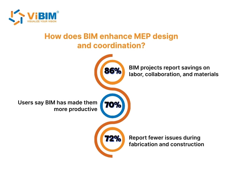
How does BIM enhance MEP design and coordination?
BIM helps MEP engineers manage the growing pressure to design systems that balance efficiency, cost, and constructability. The shared model improves collaboration, increases accuracy, and connects every element across disciplines. Design teams communicate better, make faster decisions, and create more sustainable solutions that raise the standard of project delivery.
The impact of BIM is clear in measurable outcomes:
- 86% of BIM projects report savings on labor, collaboration, and materials.
- 70% of users say BIM has made them more productive.
- 72% report fewer issues during fabrication and construction.
(Source: NBS National BIM Report, 2020)
“We saved almost 30–40% of our time. It would be impossible to have met the challenging schedule without the BIM workflow. It resulted in 20% cost savings for us and much more for the owners as we could optimize the design.”
– Bimal Patwari, Founder & CEO of Pinnacle Infotech
What are the benefits of using BIM in MEP coordination?
From early clash detection to improved collaboration, BIM ensures that MEP systems remain accurate, efficient, and cost-effective throughout every project phase. The following five key benefits demonstrate how BIM helps teams achieve better project outcomes:
- Clash Detection and Resolution: Clash detection represents one of the most valuable advantages of BIM in MEP coordination. The intelligent 3D environment automatically identifies conflicts like ducts overlapping with sprinkler lines or pipes intersecting structural beams before construction begins. This proactive process saves significant time, money, and resources by eliminating rework and ensuring a smooth on-site installation.
- Improved Accuracy and Visualization: The 3D modeling capabilities of BIM deliver superior spatial awareness compared to traditional 2D drawings. Engineers can visualize mechanical, electrical, and plumbing components in precise relation to one another, enabling optimized routing of ducts, conduits, and pipes. This accuracy enhances construction documents, improves material take-offs, and reduces the likelihood of costly design errors.
- Reduction in Rework and Errors: Automatic updates across related drawings, schedules, and views ensure that design changes propagate consistently throughout the model. This integration minimizes manual coordination errors, limits field modifications, and maintains up-to-date documentation for all project stakeholders, reducing delays and enhancing overall project reliability.
- Streamlined Prefabrication: A coordinated, clash-free BIM model allows contractors to prefabricate complex MEP assemblies off-site in a controlled environment. Prefabrication not only accelerates installation but also improves worker safety and construction quality while reducing material waste on-site.
- Enhanced Collaboration and Communication: A shared digital model unites architects, engineers, and contractors in a single collaborative workspace. Clear visualization and centralized data exchange foster transparency, strengthen trust, and enable teams to resolve challenges faster, which results in more efficient and coordinated project delivery.
What are the challenges of using BIM in MEP coordination?
While BIM delivers five major benefits for MEP coordination, its implementation also introduces technical, procedural, and human challenges. Each project requires strong planning, clear communication, and consistent standards to achieve optimal results across all disciplines.
- High Initial Implementation Cost: BIM software, hardware upgrades, and training demand substantial upfront investment. The 3d Scan to BIM cost, along with licenses, model management tools, and skilled personnel can discourage smaller firms or projects with limited budgets from adopting BIM effectively.
- Lack of Standardization and Consistent Workflows: Different firms often follow varying modeling standards and coordination processes. The absence of uniform guidelines causes inconsistencies between disciplines, leading to delays during model integration and difficulty in maintaining project-wide data accuracy.
- Complexity of Model Management: Large MEP models contain massive datasets that require high computing performance and careful file organization. Managing versions, coordinating multiple trades, and controlling model sizes can slow collaboration if workflows are not well-structured.
- Skill Gaps and Training Requirements: BIM adoption demands both technical proficiency and an understanding of collaborative workflows. Many engineers and contractors lack adequate training, which leads to inefficient model use, errors in documentation, and limited return on technology investment.
- Data Interoperability Between Software Platforms: Different building information modeling software platforms may use incompatible data formats. This creates challenges in exchanging models across design and construction teams, often requiring file conversions that risk data loss or misinterpretation during coordination.
- Resistance to Process Change: Teams accustomed to traditional 2D coordination may hesitate to shift to BIM-based workflows. This resistance affects collaboration, slows adoption, and prevents organizations from achieving the full efficiency that integrated modeling can deliver.
- High Sensitivity to Architectural, Structural, and Equipment Changes: MEP BIM modeling requires project stability across architecture, structure, and even equipment selections. A seemingly minor change can trigger extensive remodeling of multiple systems. Because design and construction naturally involve frequent revisions at various stages, MEP BIM teams face a high risk of rework and increased costs. As a result, detailed MEP BIM modeling is often reserved for technical or later-stage design phases when key decisions are more stable.
How to do MEP Coordination in BIM-based Design?
MEP coordination in a BIM-based design follows a clear and systematic workflow, comprising five essential steps: starting with the correct BIM template, validating the architectural model, developing discipline-specific MEP models, identifying clashes, and reviewing and resolving them. Each step builds accuracy and collaboration, allowing project teams to explore these stages in greater detail throughout this section.
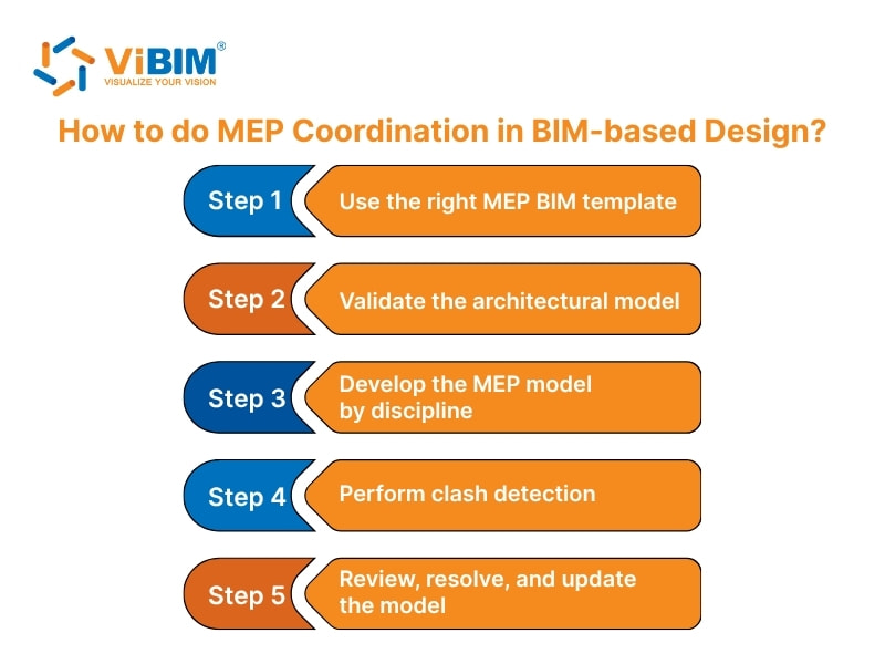
Step 1: Use the right MEP BIM template
Begin by setting up the project with a standardized MEP BIM template. This helps maintain consistency, improve coordination, and increase accuracy across all trades from the start. A well-prepared template provides a shared structure that allows every discipline to work efficiently within the same framework. The template should include:
- Predefined system classifications for each trade (Mechanical, Electrical, Plumbing, Fire Protection).
- Standardized families, annotation styles, and level of detail (LOD) settings.
- Coordination worksets and pre-configured views aligned with project deliverables.
Step 2: Validate the architectural model
Before linking MEP models, confirm that the architectural model is accurate and compatible with project requirements. This step helps teams build MEP systems on a dependable foundation, preventing alignment issues during later coordination stages.
Three key validation steps include:
- Ensuring coordinate alignment by using the “Origin to Origin” positioning method.
- Checking the completeness of spatial elements such as shafts, ceiling voids, and equipment rooms.
- Verifying that ceiling heights and clearances meet the needs of MEP systems.
Step 3: Develop the MEP model by discipline
In this step, we create separate models for each discipline, incorporating major components and system routes in a progressive manner. Coordination should be carried out across multiple dimensions to keep every system consistent with the building structure.
Within the building:
- Level by level (story by story)
- Room by room (including below raised floors)
- Horizontal spaces (plenums)
- Vertical spaces (shafts and cores)
Outside the building:
- Mechanical systems: HVAC equipment, ducting, chillers, etc.
- Plumbing systems: Pumps, tanks, sump pits, filtration units.
- Fire protection systems: Sprinkler pumps, smoke curtains, piping.
- Electrical systems: Panels, switchboards, transformers, cable trays.
Step 4: Perform clash detection
Once models are developed, use coordination software such as Autodesk Navisworks to identify and evaluate conflicts between different systems. This process enables design teams to refine layouts prior to construction, thereby reducing on-site issues.
An effective clash detection process involves:
- Running tests between disciplinary models to locate physical and clearance issues.
- Categorizing clashes by type and assigning them to responsible teams.
- Prioritizing major system conflicts before addressing minor ones.
- Tracking issues through regular coordination meetings.
To move from strategy to execution and learn how to set up these specific test rules within the software, follow our step-by-step guide on Navisworks clash detection.
Step 5: Review, resolve, and update the model
The final step focuses on reviewing detected clashes and updating the models accordingly. A systematic resolution workflow includes:
- Reviewing each clash to evaluate design options and identify the most practical solution for the affected systems.
- Fixing all detected issues directly in Revit so every model remains accurate and coordinated.
- Rerunning clash detection after revisions to confirm that the adjustments have not created new conflicts.
- Updating the central model to serve as the single and most current source of information for all design disciplines.
Best practices for MEP consultants using BIM
To maximize the efficiency and accuracy of BIM-based MEP coordination, consultants need to follow a set of best practices, from establishing clear standards to using modern collaboration tools. These practices help maintain consistency, reduce design conflicts, and deliver better outcomes across every project phase.
- Establishing clear BIM execution plans: A BIM plan defines modeling standards, workflows, and responsibilities before the project starts. It also includes LOD requirements for each stage to set clear expectations for all participants.
- Implementing a graduated approach to clash detection: A structured process begins with major systems and gradually moves to smaller components. This keeps coordination manageable while allowing design teams to focus on high-impact conflicts first.
- Investing in proper training and support resources: Training programs and technical support help teams adapt faster to BIM workflows. Continuous coaching enables users to maintain consistency and accuracy across disciplines.
- Creating standardized clash detection frameworks and templates: Defining clash rules and templates helps distinguish critical design issues from minor ones. Custom frameworks also enhance coordination by aligning with project-specific goals.
- Utilizing cloud-based collaboration platforms: Shared online environments provide all stakeholders with access to real-time data and models. This approach keeps every team member aligned and reduces the risk of outdated information during coordination.
The article has explained what BIM for MEP is and how it supports engineers in designing and coordinating building systems with accuracy and efficiency. Each section outlined the modeling workflow, coordination steps, and practical methods that help teams detect clashes, organize models, and improve project delivery through better collaboration. By clarifying how BIM enhances communication between disciplines, the content addressed the reader’s need to understand how this approach streamlines MEP processes and strengthens design consistency.
Drawing from these principles, ViBIM has delivered numerous projects using our MEP Scan to BIM Services, applying the same coordination methods, modeling standards, and workflow logic described above. Our team supports clients across design development, technical coordination, and as-built verification, ensuring every model meets the required accuracy for mechanical, electrical, and plumbing systems.
Contact ViBIM today to discuss your Revit BIM outsourcing services requirements and receive a complimentary quote for the best services.
Vietnam BIM Consultancy and Technology Application Company Limited (ViBIM)
- Address: 10th floor, CIT Building, No 6, Alley 15, Duy Tan street, Cau Giay ward, Hanoi, Vietnam
- Phone: +84 944 798 298
- Email: info@vibim.com.vn