Business Needs
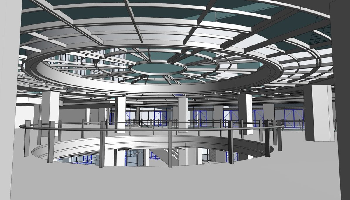
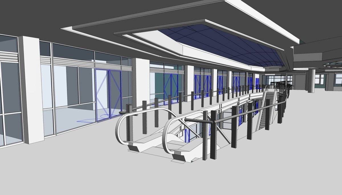
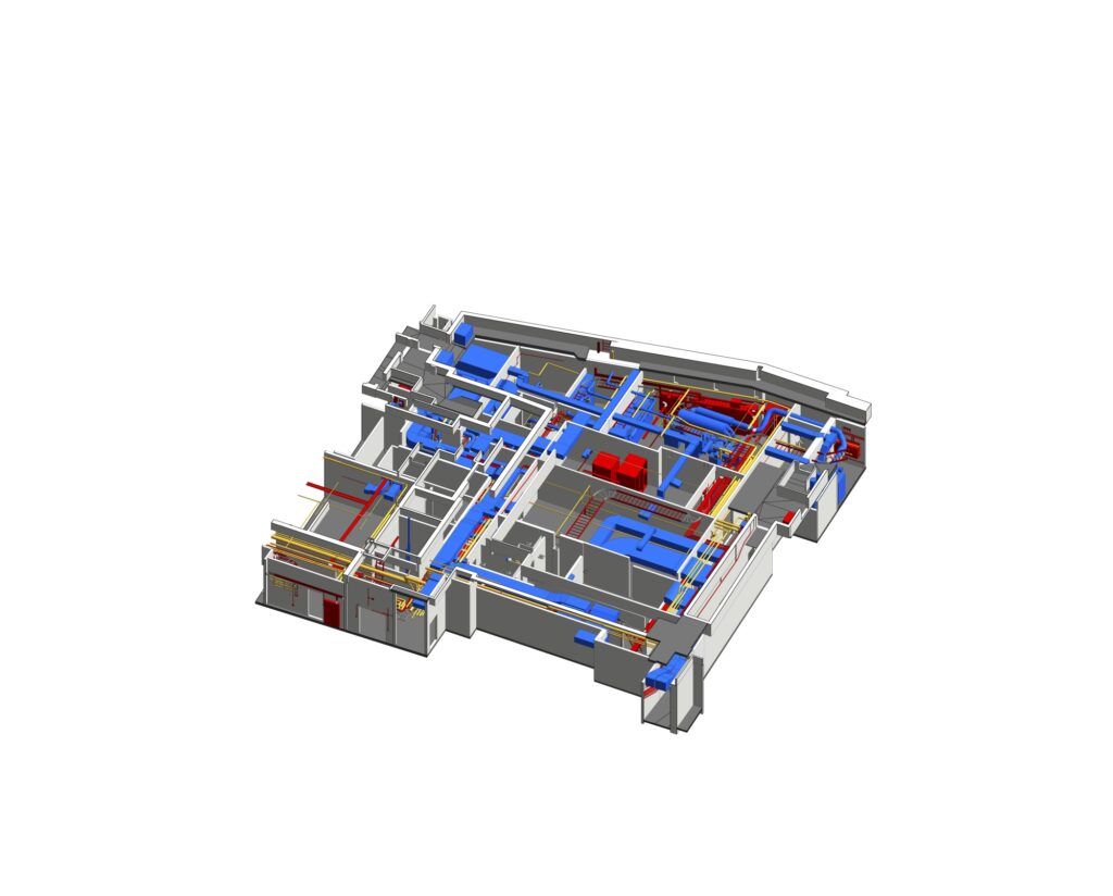
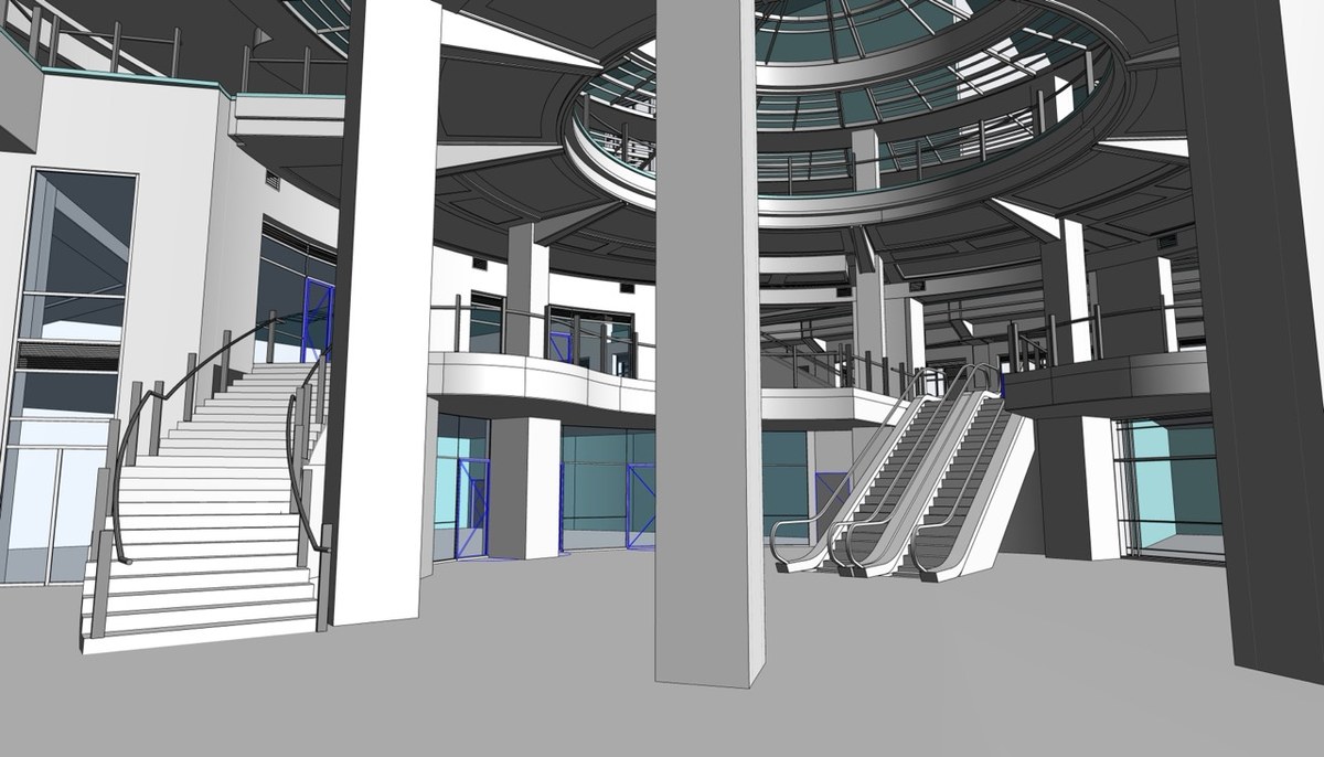
Four basement levels and a curved facade give this building a great deal of structure that never shows on a clean set of drawings, above ground or below. The client wanted all of it recorded as an architecture and structure model, true to the real geometry, dimensions, and levels of every part, so it could serve future maintenance, renovation, and design work. Because the structure is dense and the facade is curved, the model had to reproduce real conditions rather than rely on assumptions.
Working with a structurally complex or multi-level existing building? ViBIM’s Point Cloud to BIM Service reconstructs an accurate Revit model of what is really there, below ground and above.
Key Objectives
- An Accurate LOD 300 As-Built Model: Build a 3D architecture and structure model from point cloud and site images, held within ±15 mm (±0.6 in) of the scan through point cloud to Revit conversion, reflecting a building with dense basements, split-level floors, and a curved facade.
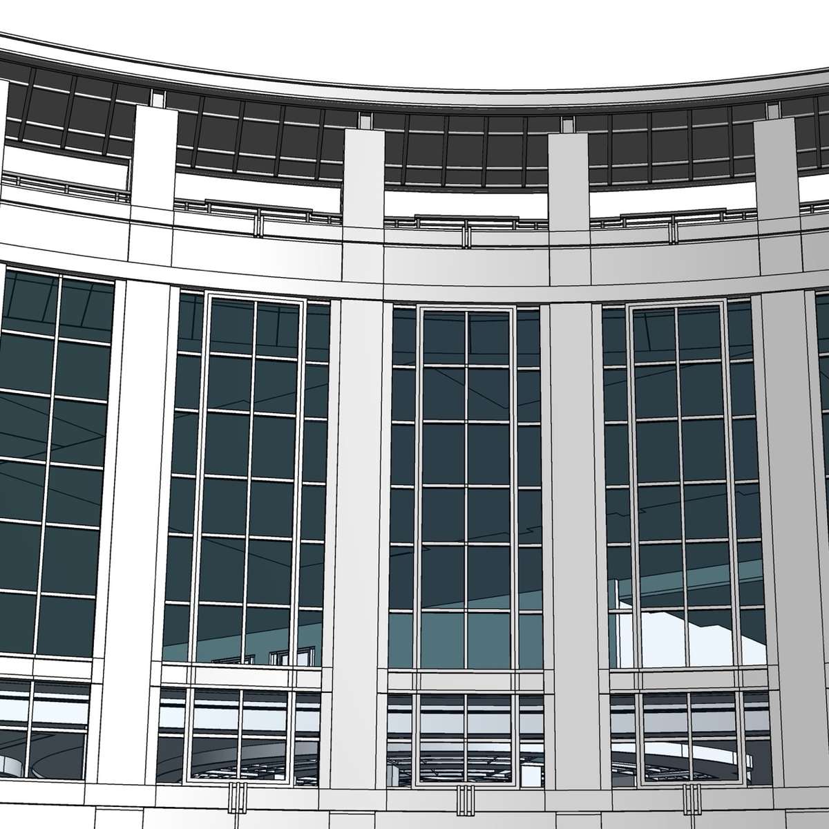
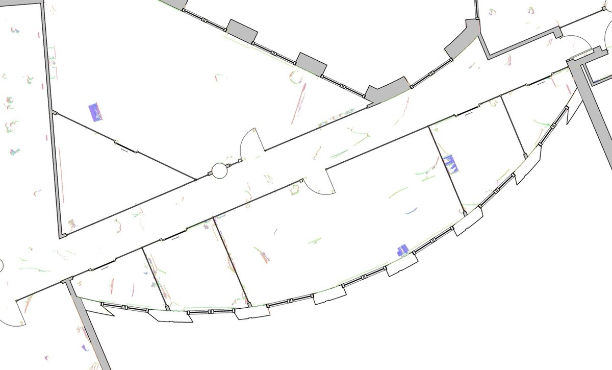
- Faithful Curved Geometry: Reproduce the curved facade walls and curved windows as smooth, continuous elements, with the windows matched to the exact radius of the walls that hold them.
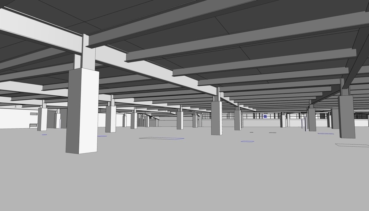
- Accurate Structural Connections: Capture the dense column, beam, and wall junctions through the basement levels, keeping vertical elements aligned floor to floor.
Challenges
A curved shell over four packed basements pushes a scan-to-BIM team on two fronts at once. How do you rebuild a smooth curved facade from scattered points, and still keep a dense structural frame aligned through every level below?
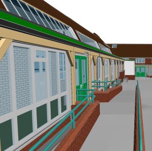
- Curved Walls and Curved Windows: A curved facade makes it hard to read the true edge levels of floors and roof and the parametric curve of the walls. Turning curved point cloud data into a smooth, unbroken BIM surface takes real skill, and the windows added a second layer: each curved window had to be built with the right parameters and matched perfectly to the curve and lean of the wall around it, which meant custom objects rather than standard families.
- Split-Level Floors: Stepped floor slabs and split-level basement structure meant each transition in height had to be measured and modeled separately and precisely.
- Dense Structural Connections: The high density of columns, beams, and walls at the basement junctions made the real connections hard to read and model. With registration error a constant risk, vertical elements could drift sideways between floors, leaving beams that would not sit correctly on the columns above or below.
- Four Wide Basement Levels: Four car-park basement levels spread over a large footprint made it difficult to match floor points accurately across such a wide area.
Our Solutions and Approach
ViBIM tackled the building within its Scan to BIM workflow, solving the curved geometry and the dense structure with method rather than guesswork. The team took the curves and the structure in turn:
- Rebuilding the Curved Facade: To find the wall’s true curve, the team sliced the point cloud into thin horizontal bands at several heights and fitted a reference circle to each. Averaging the center and radius over three or four of those bands cancelled out the scan noise and fixed one dependable arc, so the facade could be modeled as a single smooth wall instead of a run of short straight segments. The windows needed the same care, so rather than standard families the team built a custom window whose radius and rotation could be dialed in to sit flush against the curve.
- Modeling Split Levels: The team cut detailed sections through the stepped and split-level areas to verify each height from the point cloud, modeled the floor slabs first as reference masses, and broke the work down by basement level and smaller zones to keep it under control.
- Resolving Dense Connections: Column-to-beam and wall-to-beam junctions were modeled with their real openings and gaps, using 3D section views together with site photos to isolate each junction in the point cloud and reproduce the actual overlapping geometry.
Business Impact
- An Earlier, Smoother Start for Design Teams: With the model built to the point cloud within ±15 mm, accurate existing-condition data was ready for the architecture, structure, and M&E teams to begin work sooner and with fewer interruptions from missing measurements, which sped the project up and helped control management cost.
- A Reliable Digital Asset Record: The detailed model becomes an accurate record of where the dense columns, beams, walls, and curved windows actually sit, so the facility team can find asset information quickly and plan maintenance, repairs, and upgrades with confidence.
Got a multi-level building with structure that never shows on clean drawings? That is the kind of job ViBIM’s 3D BIM modeling services take on, below ground and above.