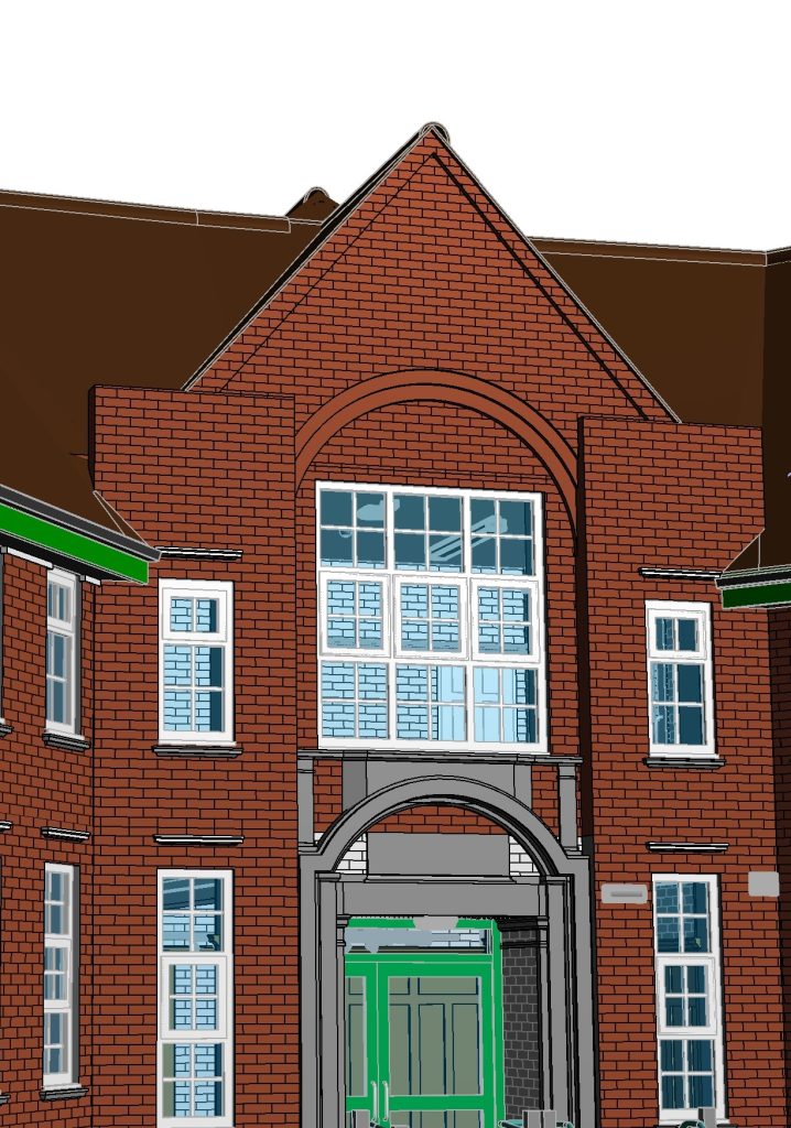
Business Needs
Years of undocumented changes had left this aging commercial building without a reliable record of what was actually there. The client wanted one, a complete as-built model covering every architectural, structural, and MEP element inside and out, built to a consistent LOD 300 so a single model could serve renovation planning, design coordination, and long-term facility management. Because the building pairs non-standard geometry with dense building services, the model had to capture the real site conditions rather than rely on original drawings that no longer match the space.
Planning a renovation or refit of an existing commercial building? ViBIM’s Scan to BIM Service builds a coordinated Revit model from dense point cloud data, ready for design and facility-management decisions.
Key Objectives
- An Accurate LOD 300 As-Built Model: Produce a 3D Revit model of the entire building, spanning architecture, structure, and MEP, that reflects true as-built conditions through point cloud to Revit conversion.
- Faithful Complex Geometry: Reproduce the curved roof and the non-orthogonal walls as smooth, continuous elements, holding geometric deviation to within ±15 mm (±0.6 in) of the source scan.
- An Operational Data Foundation: Deliver a model detailed enough to support later renovation design, spatial planning, and facility management, with correct non-geometric data such as materials and specifications attached to each element.
Challenges
Reproducing a building with this mix of organic geometry and dense services raised several technical hurdles. How do you hold a model to a ±15 mm tolerance when the as-built conditions work against you at almost every element?
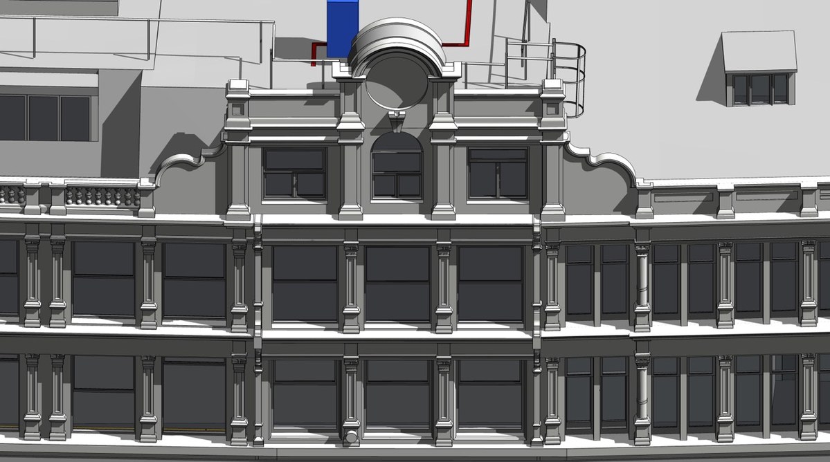
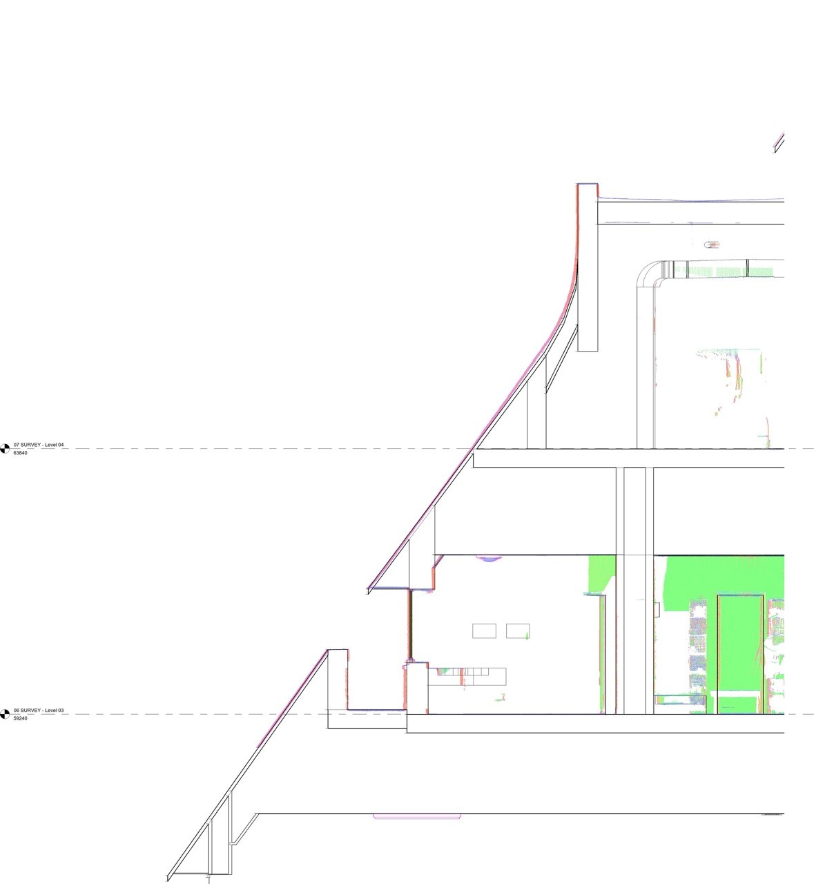
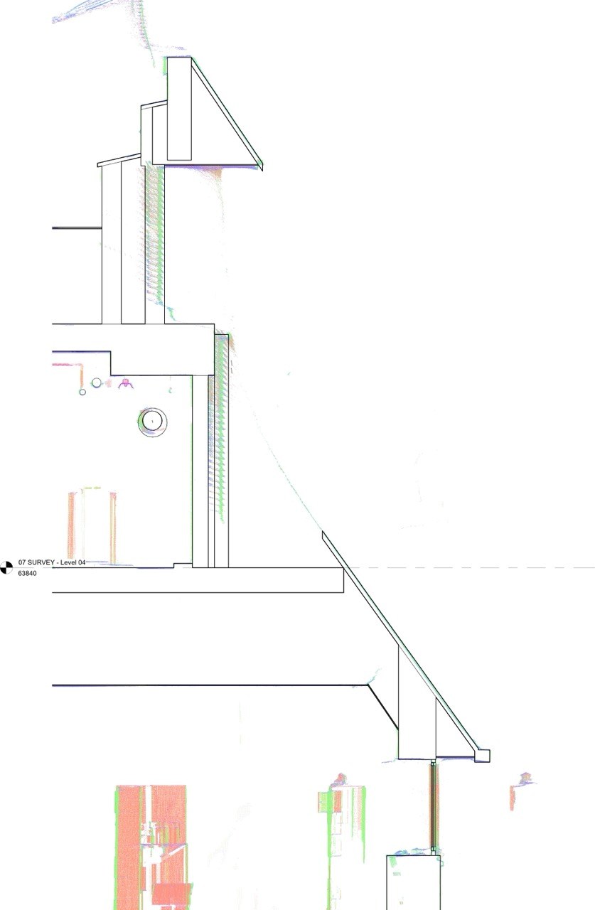
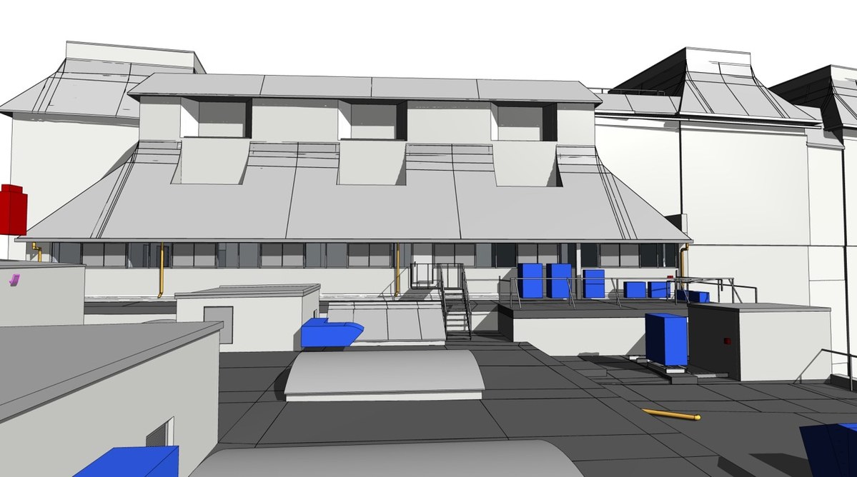
- Complex Curved Roof Geometry: A curved roof rarely follows standard parametric shapes, so converting it from the point cloud into a smooth, continuous BIM object called for custom spline and arc work and a precise reading of the true radius. Roofs also carry few vertical reference details and sit exposed to wind during scanning, which makes registering scan points to an accurate absolute elevation (Z-axis) difficult. Any error at the ridge or eaves would throw off the connection between the roof and the floors below.
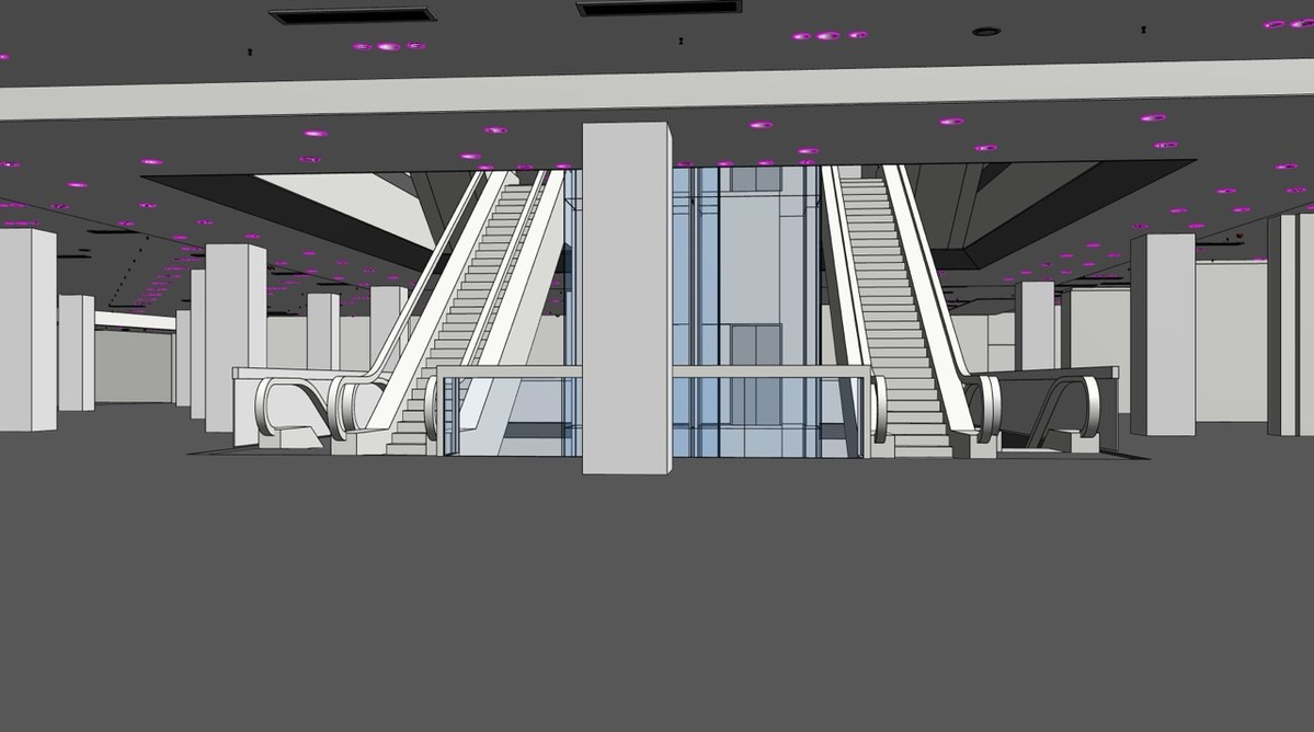
- Non-Orthogonal Plan and Walls: Slanted, non-perpendicular walls demanded far more manual modeling and tighter tolerance control than straight walls. The irregular layout also limited copy-and-paste reuse between floors, so each level had to be modeled individually against its own point cloud slice, which added considerable time.
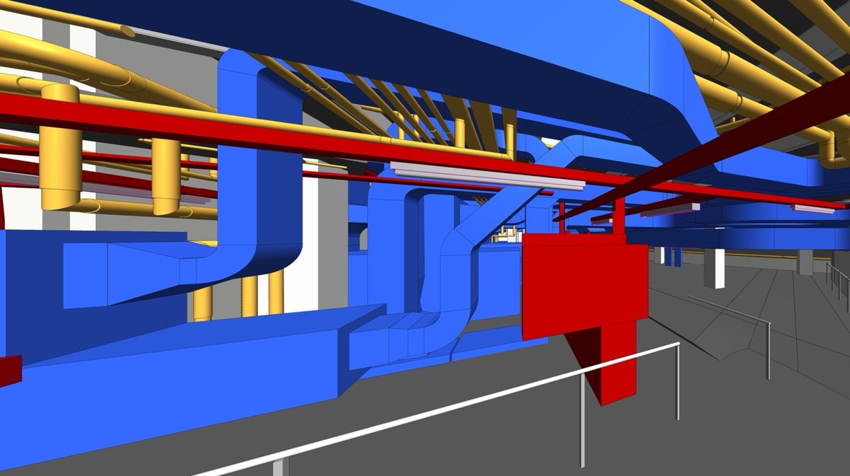
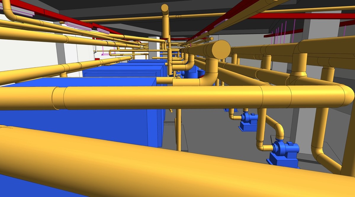
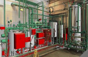
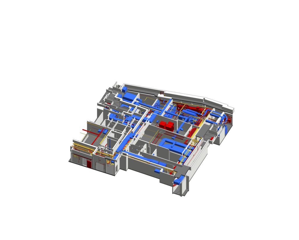
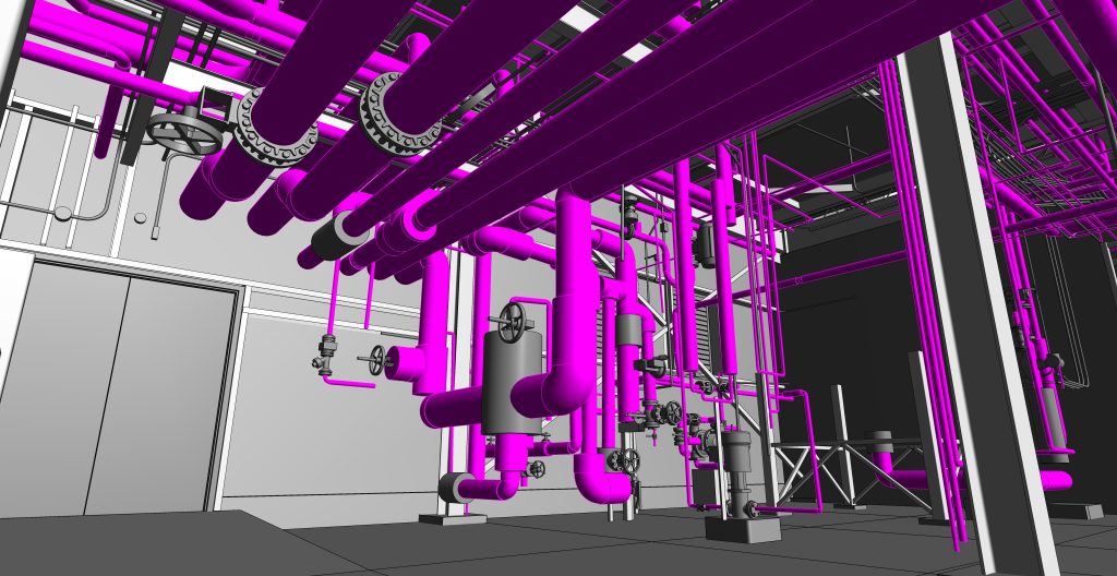
- Dense MEP Systems: The large technical rooms carried thick, multi-size HVAC ductwork that branched down through the lower ground and basement levels. Ceilings were packed with lights, decorative fittings, and air terminals set side by side, while long parallel plumbing runs forced constant section adjustments to model accurately.
- Ambiguous Fire-Protection Data: Small-diameter sprinkler pipework and heads ran tight against the ceiling and appeared blurred in the point cloud, so objects were easy to miss and the review stage carried heavy pressure. Scattered electrical panels and cable trays added to the risk of omissions.
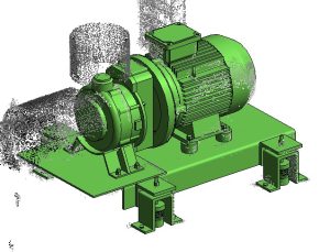
- Family Precision and Embedded Data: Every family had to match its real object in material, size, weight, and capacity, held to a ±15 mm (±0.6 in) geometric tolerance and populated with complete non-geometric BIM information, which left little margin for error.
Our Solutions and Approach
Within its Scan to BIM workflow, ViBIM met these challenges with a specialist-led approach and continuous, parallel quality control. Each front was handled as follows:
- Modeling the Curved Roof: The team read key horizontal and vertical roof sections from the point cloud, extracted 3D reference curves from those sections, and built a mass and surface that matched the scan. Revit’s Roof by Face function then applied thickness and material, and a dedicated deviation-analysis tool confirmed the finished roof stayed true to the point cloud.
- Resolving Irregular Walls and Layouts: Engineers measured each wall’s real angle against the main grid and worked only from point cloud data cropped to the floor in hand. After finishing a level, they checked its junctions with the floors above and below, with particular attention to vertical elements like columns and cores. A live 3D view with the point cloud as background let them draw and verify each element directly, and a 3D section box isolated the most complex areas for closer detailing.
- Specialist-Led MEP Modeling: Rather than split the dense services across the team at random, ViBIM assigned its most experienced engineers to the hardest systems:
- HVAC: one engineer owned the full system, starting from the main plant rooms and following the technical risers, which kept the reasoning continuous and moved the complex duct runs along efficiently.
- Fire protection: a dedicated specialist learned to read the blurred point cloud signatures of the small pipes and sprinkler heads, which sharply cut the chance of missed objects.
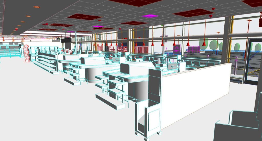
- Ceiling-mounted equipment: one member swept every ceiling fixture using combined 2D sections and the 3D model, so nothing in the dense array slipped through.
- Zone-Based Coverage for Scattered Elements: For the plumbing, electrical panels, and cable trays spread across the building, the team divided the project into clearly bounded zones, each one owned by a single modeler responsible for every MEP object inside it.
- Parallel Quality Control: As modeling progressed, members cross-checked their work against the Revit model, Navisworks, and detailed sections at the same time, so issues surfaced and were resolved immediately instead of stacking up for a final pass.
- Accuracy and Data Integrity: Internal automation tools sped the work while holding the ±15 mm (±0.6 in) tolerance, and each element received accurate non-geometric information, covering materials, capacity, and technical specifications, so the model mirrored the real building.
Business Impact
- A Curved Roof That Matches the Scan: The roof was built as one continuous surface from sections cut through the point cloud rather than pieced together from flat segments, and deviation analysis checked the finished roof against the scan. The client has a true record of the part of the building that original drawings described least, with ridge and eaves set where they actually are and a roof that meets the floors below correctly.
- Eight Irregular Floors That Line Up: Each level was modeled from its own point cloud slice and checked at its junctions with the floors above and below, so the slanted walls, columns, and cores stay aligned from top to bottom within the ±15 mm (±0.6 in) tolerance, even though the plan offered almost no repeatable floor to copy.
- Dense Services Modeled, Not Missed: With one specialist each on HVAC, fire protection, and ceiling equipment, and zone ownership for everything else, the blurred sprinkler runs and tightly packed ceiling fixtures made it into the model instead of slipping through. The MEP record follows the ductwork from the plant rooms down to the basement as it is actually installed.
Curved roofs, off-grid walls, and packed plant rooms are where as-built models usually lose accuracy. ViBIM’s Revit Modeling Services keep them true to the scan.